


– 11 –
ICX423AL
Light
Signal output 350mV Vlag (lag)
FLD
V1
Strobe light
timing
Output
1
10
1
500
VSm
350
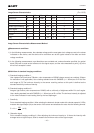
3. Smear
Set to standard imaging condition II. With the lens diaphragm at F5.6 to F8, adjust the luminous intensity to
500 times the intensity with average value of the signal output, 350mV. When the readout clock is stopped
and the charge drain is executed by the electronic shutter at the respective H blankings, measure the
maximum value (VSm [mV]) of the signal output and substitute the value into the following formula.
Sm = 20 × log × × × 100 [dB] (1/10V method conversion value)
4. Video signal shading
Set to standard imaging condition II. With the lens diaphragm at F5.6 to F8, adjust the luminous intensity so
that the average value of the signal output is 350mV. Then measure the maximum (Vmax [mV]) and
minimum (Vmin [mV]) values of the signal output and substitute the values into the following formula.
SH = (Vmax – Vmin)/350 × 100 [%]
5. Dark signal
Measure the average value of the signal output (Vdt [mV]) with the device ambient temperature 60°C and
the device in the light-obstructed state, using the horizontal idle transfer level as a reference.
6. Dark signal shading
After measuring 5, measure the maximum (Vdmax [mV]) and minimum (Vdmin [mV]) values of the dark
signal output and substitute the values into the following formula.
∆Vdt = Vdmax – Vdmin [mV]
7. Flicker
Set to standard imaging condition II. Adjust the luminous intensity so that the average value of the signal
output is 350mV, and then measure the difference in the signal level between fields (∆Vf [mV]). Then
substitute the value into the following formula.
F = (∆Vf/350) × 100 [%]
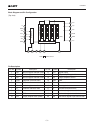
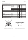
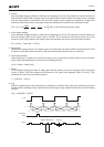
8. Lag
Adjust the signal output value generated by strobe light to 350mV. After setting the strobe light so that it
strobes with the following timing, measure the residual signal (Vlag). Substitute the value into the following
formula.
Lag = (Vlag/350) × 100 [%]