


-22-
For Machines Mfg. Since 8/09
Model SB1023
OPERATION
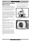
Removing & Installing
Wheel & Hub
To remove and reinstall the wheel and hub:
1. DISCONNECT MACHINE FROM POWER!
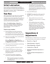
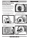
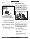
2. Place a sheet of plywood or similar on top of
table to protect the table (Figure 20), and
open the grinding wheel cover.
When the wheel has been ring tested, and
dressed, the wheel and hub must be removed and
balanced as an assembly. However, remember
that overtightening or rotating the spindle bolt in
the incorrect direction can damage threads, crack
the grinding wheel, and make grinding wheel
removal more difficult than it needs to be.
When removing and installing the hub onto the
spindle or balancing arbor, keep in mind that the
mating surfaces between these components have
the single most important effect on your final
balancing results. Hubs, spindles, and balancing
arbors can be easily damaged during installation
and removal. Just one grain of sand, small burr,
or hidden ding in either mating surface will
undermine all balancing results. Make sure
that all mating surfaces are carefully stoned to
establish a perfect fit.
NEVER pound on a hub or arbor for any reason.
This will permanently displace metal and change
high tolerance dimensions.
NEVER use a hydraulic press to install the
balancing arbor or attempt to use a heat
differential between parts to establish a shrink-
fit. This will change high tolerance dimensions.
NEVER twist-fit the hub onto the spindle or
the balancing arbor. Doing this can gall the
tapered surfaces. Instead use a small arbor press
with light pressure to install and remove the
balancing arbor from the hub.
ALWAYS make sure that all mating surfaces
are immaculately cleaned before hub or arbor
installation. Use a lint-free photography lens
cloth that is slightly oiled with a thin machine
oil. For the best fit, the mating surfaces must
be polished without having a wet layer of oil on
them. The oil should only be in the pores of the
metal.
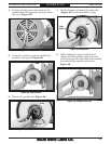
Figure 20. Protecting the table.
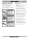
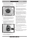
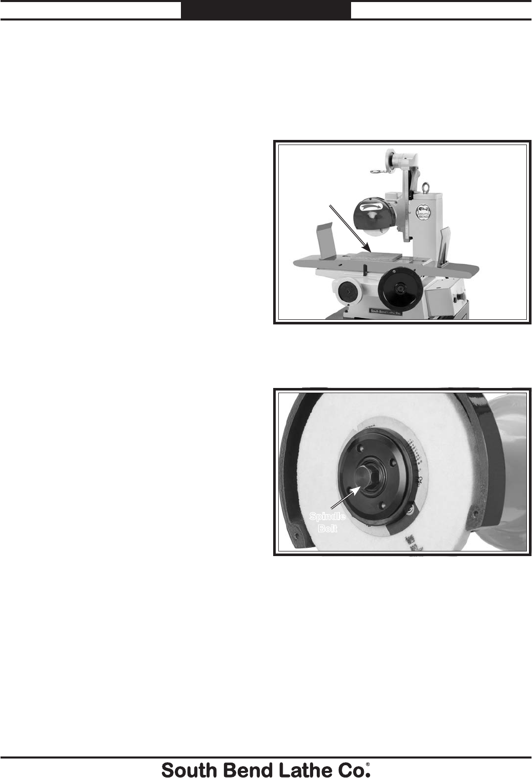
3. Position the spindle wrench on the spindle
bolt (Figure 21).
Figure 21. Retaining fasteners.
Spindle
Bolt