


For Machines Mfg. Since 8/09 SB1024/SB1025/SB1026
-27-
PREPARATION
Inspections &
Adjustments
The following list of adjustments were performed
at the factory before the machine was shipped:
s Gib Adjustment .................................Page 58
s Leadscrew Backlash
Adjustment .........................................Page 59
Be aware that machine components can shift
during the shipping process. Pay careful
attention to these adjustments during operation
of the machine. If you find that the adjustments
are not set according to the procedures in this
manual or your personal preferences, re-adjust
them.
Spindle Break-In
The high-quality bearings and gears used in the
mill are manufactured to very close tolerances.
However, this does not guarantee perfect
dimensional mating of the bearing components or
exact meshing of gear teeth. Before operational
stress is placed on these and other moving parts
in the mill, complete this break-in procedure to
conform these components to one another and
ensure trouble-free performance from the mill.
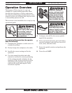
To perform the spindle break-in procedure:
1. Successfully perform all the steps in the
Test Run section beginning on Page 25.
2. Make sure the spindle is at a complete stop.
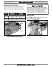
3. Set the spindle speed to the low range
(refer to Setting Spindle Speed Range
beginning on Page 37 for detailed
instructions).
4. Start the spindle rotation at a medium speed
and let the mill run for 20 minutes.
5. Stop the spindle rotation and allow the
spindle to come to a complete stop by itself.
6. Set the spindle speed to the high range, then
start the spindle rotation at a medium speed
and let the mill run for another 20 minutes.
7. Stop the spindle rotation, and turn the mill
OFF.
The spindle break-in of the mill is now complete!
Complete the spindle bearing break-in
procedure to avoid rapid deterioration of
spindle components when the mill is placed
into operation.
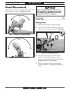
Since the mill head was rotated parallel to
the table for shipping purposes, you will need
to tram the spindle with the table if your first
cut requires a 90° alignment. Refer to the
Tramming Spindle section on Page 33 for
detailed instructions.