


For Machines Mfg. Since 8/09 SB1024/SB1025/SB1026
-29-
OPERATION
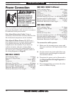
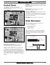
Control Panel
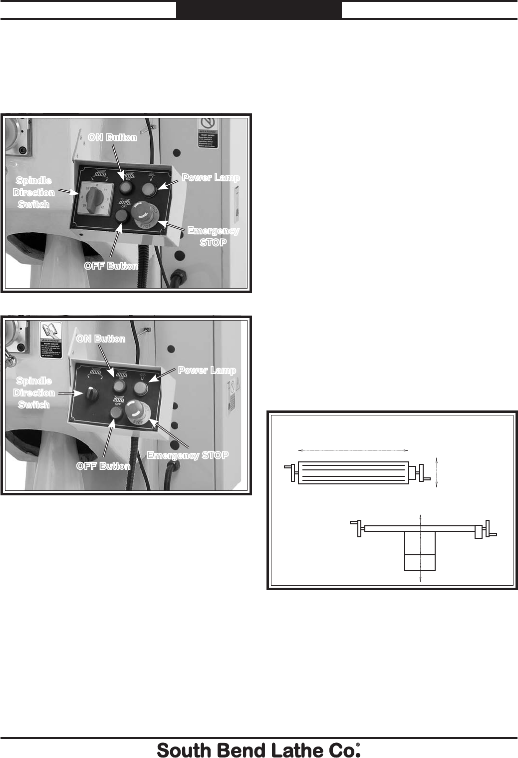
Use Figures 15–16 and the following
descriptions to understand the functions of the
mill control panel.
ON Button: Allows power flow to the motor. The
spindle direction switch must be used to start the
spindle rotation.
Power Lamp: Illuminates when the mill is
connected to a power source.
Emergency STOP Button: Stops the flow of power
to the motor. Twist clockwise until it pops out to
reset it, then press the ON button to re-establish
power flow to the motor.
OFF Button: Stops power flow to the motor.
Spindle Direction Switch: Starts, stops, and
reverses the direction of spindle rotation.
Note: The Model SB1025 has two positions for
each direction that electronically change the
speed of the motor and work in conjunction with
the belt housing controls to set the spindle speed
range (refer to "To set the spindle speed range
for the Model SB1025" on Page 39 for additional
details).
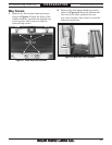
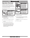
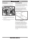
Table Movement
The mill table moves in three directions, as
illustrated in Figure 17:
s X-axis (longitudinal)
s 9AXISCROSS
s :AXISVERTICAL
These movements are controlled by table ball
HANDLESANDTHE:AXISCRANK!DDITIONALLYTHE
table can be moved along the X-axis with the
power feed.
Figure 17. The directions of table movement.
X-Axis or Longitudinal Travel
(Left & Right)
Y-Axis or
Cross Travel
(In & Out)
Z-Axis or Vertical Elevation
(Up & Down)
Figure 15. Model SB1025 control panel.
Spindle
Direction
Switch
Power Lamp
Emergency
STOP
ON Button
OFF Button
Figure 16. Model SB1024/SB1026 control panel.
Spindle
Direction
Switch
Power Lamp
ON Button
OFF Button
Emergency STOP