


-34-
For Machines Mfg. Since 8/09
SB1024/SB1025/SB1026
OPERATION
Tools Needed Qty
Dial Test Indicator
(with at least 0.0005" resolution) ..................1
Indicator Holder
(mounted on the quill/spindle) ......................1
Precision Parallel Block
(at least 9" in length) .....................................1
Note: A precision-ground plate can be substituted
for the parallel blocks. Keep in mind that the
farther the indicator point can be placed from the
spindle axis, the more accurate the alignment
measurements will be.
To tram the spindle to the table:
1. DISCONNECT MILL FROM POWER!
2. Prepare the mill by performing the following
tasks:
s 3TONETHETABLETOREMOVEALLNICKSAND
burrs, then clean off all debris. Verify the
table is clean by running your hand over
the top of it.
s 0OSITIONTHETABLEFORTHEMILLING
operation you intend to perform after the
tramming—preferably centered to the
saddle.
s 4IGHTENANYTABLEKNEEQUILLORRAM
locks that should be tight during the
intended milling operation.
3. Place the parallel block underneath the
spindle.
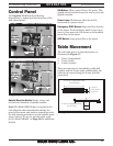
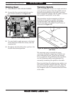
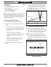
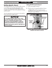
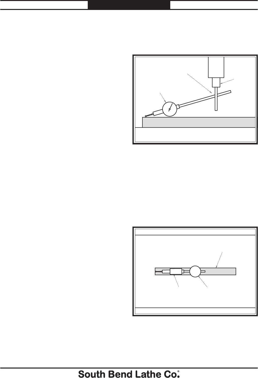
Figure 26. Dial test indicator mounted.
Table
Spindle
Dial Test Indicator
Indicator Holder
Parallel Block
4. Install the indicator holder into the spindle
or onto the quill, then mount the indicator
onto it so that the point is as parallel to
the block as possible (see the illustration in
Figure 26 for an example).
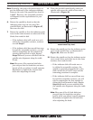
5. To measure spindle alignment along the
X-axis, place the parallel block directly under
the spindle and indicator across the length of
the table, as illustrated in Figure 27.
Note: If you must re-position the quill or the
knee to accommodate the above step, then
review the tasks in Step 2 to make sure the
mill is properly prepared for the tramming
operation.
Figure 27. Parallel block positioned for the X-axis
measurement (top view).
Parallel Block
Indicator
Spindle
Table (Top View)