


Camlock Stud Installation
Thecamlockstudsthatareshippedwiththis
chuckmaybepre-installedfromthefactory.
IfsoskipthissectionandcompleteChuck
Installation and Removal on Page 4;
otherwise,installthecamlockstudsasoutlined
below:
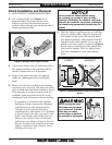
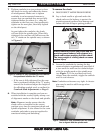
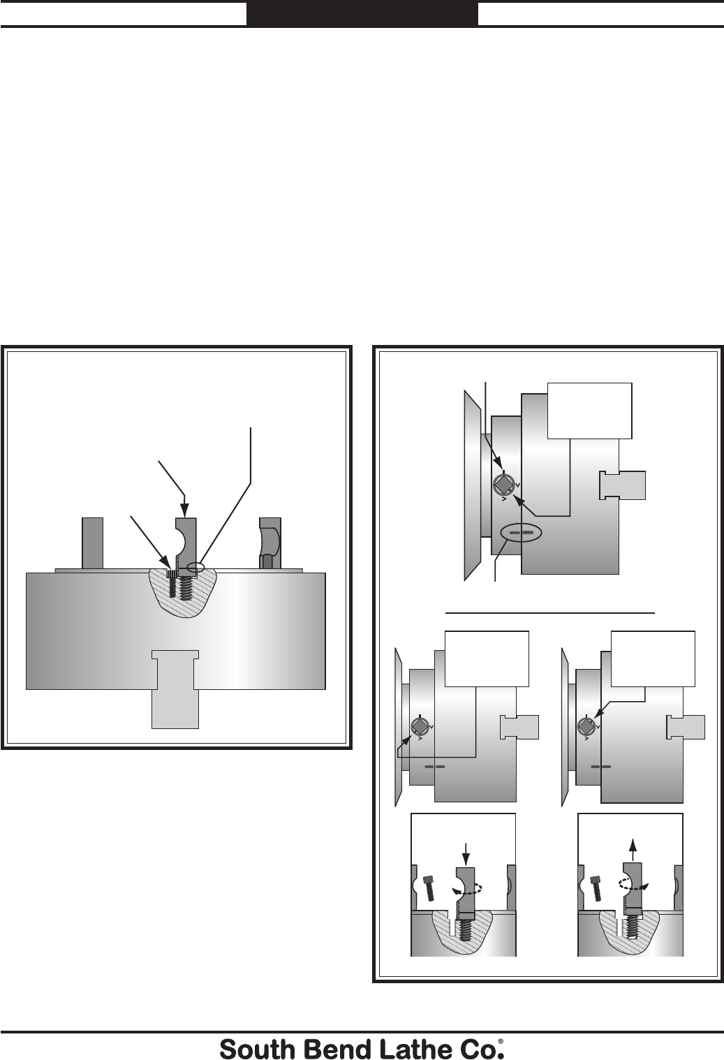
1. Oilandthreadeachcamstudintothechuck
untilthealignmentgrooveisushwiththe
chucksurface,asshowninFigure 2.
2. Installandtightenthelockingcapscrew
foreachstud,makingsurethatthecamlock
studscanslightlyrotatebackandforth.
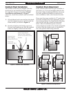
Figure 2. Camlock stud installation.
Figure 3. Camlock stud adjustment.
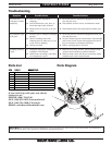
Camlock Stud Adjustment
Ifthecamlockstudshavebeenpre-installedat
thefactory,orifyouareinstallingthemforthe
rsttime,slightmachiningdifferencesbetween
thelathespindleandchuckcancauseoneor
morecamlockstolockattheincorrectlocation.
If any cam line stopsoutsideofa “V” mark when
allofthecamlockshavebeentightened, remove
thechuckandadjusttheheightoftheoffending
stud one full turn up or down asillustrated
below.Afterallcamlocksoperatecorrectly,
stampalignmentmarksinthechuckandspindle
toensurethatthechuckcanbere-installedin
thesamepositionafterbeingremoved.
Camlock Stud
Must Slightly
Rotate Back/Forth
Cap Screw
Installed & Tight
Initial Adjustment:
Camlock Stud Alignment
Groove is Flush with Chuck
Surface
Alignment Marks
Spindle Line
CORRECT
The Camlock Mark
Stops Between the
“V” Marks.
To Correct:
Turn Stud One Turn In
To Correct:
Turn Stud One Turn Out
INCORRECT
The Camlock Mark
Stops Before the
“V” Marks.
INCORRECT
The Camlock Mark
Stops After the
“V” Marks.
Mfg.Since5/10 Model SB1231
-3-
INSTRUCTIONS