


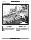
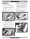
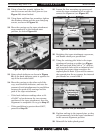
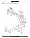

Figure 16. Deadman and arm installation.
Deadman
Clamp Cap
Screw
Deadman
Arm
Arm
Clevis
Arm Clamp
Cap Screw
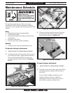
29. Rotate, push in, or pull out the adjustment
cam to adjust the deadman arm so it is as
parallel as possible with the lathe bed in
both the vertical and horizontal plane.
Note: You may have to rotate the deadman arm
so the arm clevis allows the arm to be tilted
in a particular direction.
— To tilt the arm in the vertical plane, rotate
the knurled adjustment cam.
— To tilt the arm in the horizontal plane, slide
the adjustment cam in or out of the deadman
housings.
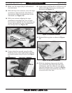
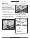
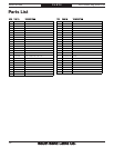
Figure 18. Saddle gap.
Complete Travel Without
Deadman Clamp Contact
1" Saddle
Safety Gap
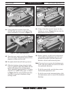
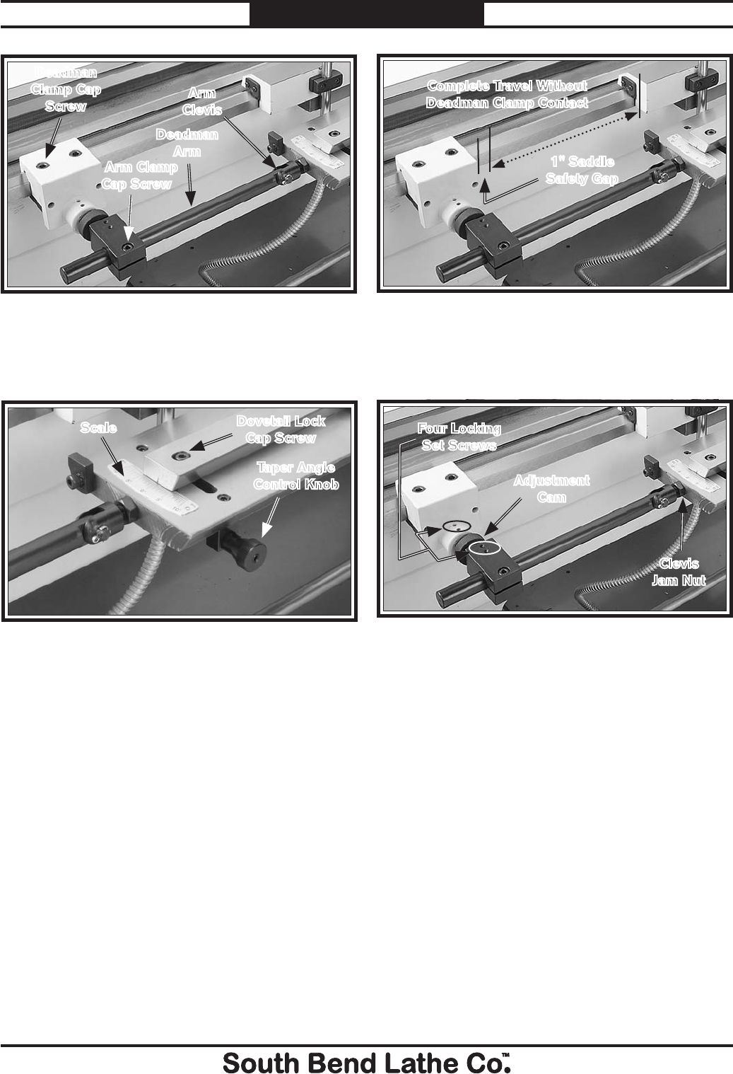
28. Using a 3mm hex wrench, loosen the four
locking set screws (Figure 19) that lock the
adjustment cam in position.
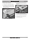
24. Using a 6mm hex wrench, loosen the
dovetail lock cap screw at each end of the
taper attachment, as shown in Figure 17.
Figure 19. Deadman arm alignment.
Four Locking
Set Screws
Adjustment
Cam
Clevis
Jam Nut
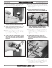
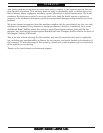
Figure 17. Taper angle adjustment.
Dovetail Lock
Cap Screw
Taper Angle
Control Knob
Scale
25. Turn the taper angle control knob (Figure
17), so the taper attachment points to zero
degrees as shown on the scale.
26. Re-tighten both dovetail lock cap screws.
27. Slide the deadman clamp along the lathe
way to a position where the saddle will not
contact the clamp when cutting tapers.
There should be approximately 1" of safety
clearance or "saddle safety gap," as shown
in Figure 18. You must double check this
clearance to prevent a deadman clamp
carriage crash.
-8-
For Product Mfg. Since 1/10
Model SB1269
PREPARATION