


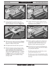
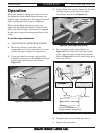

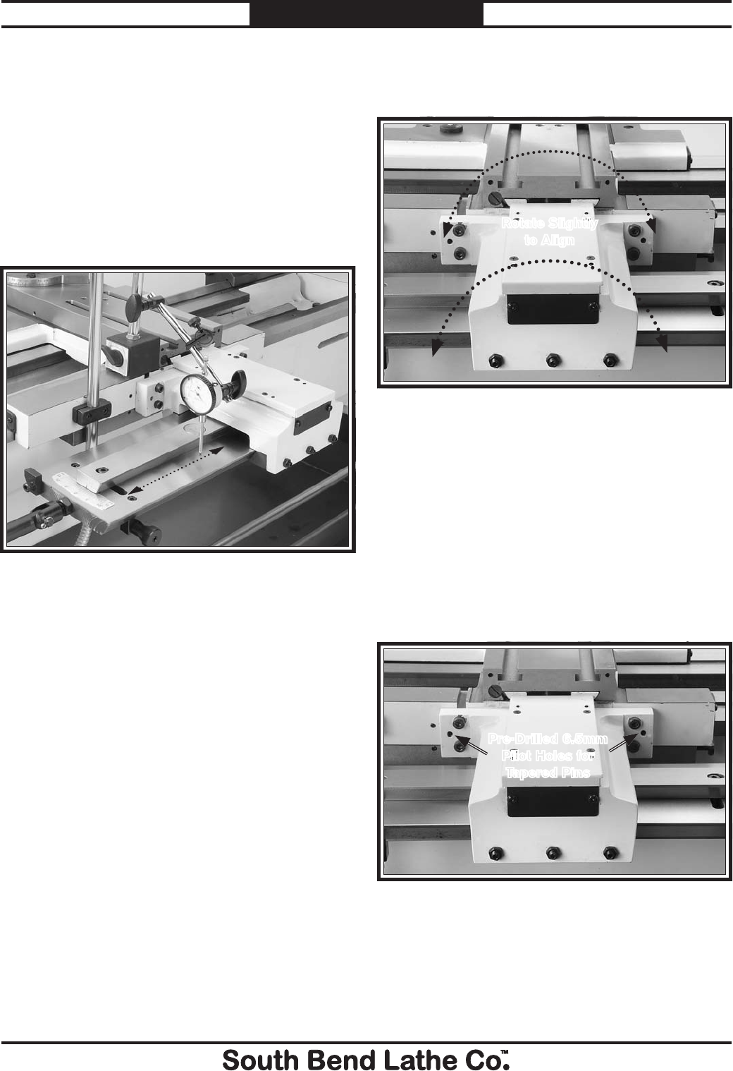
35. Loosen the four mounting cap screws and
rotate the taper attachment left or right to
correct the alignment (see Figure 21).
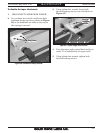
Figure 22. Roll pin installation.
Pre-Drilled 6.5mm
Pilot Holes for
Tapered Pins
36. Retighten the taper attachment cap screws,
and double check your parallelism.
37. Using the existing pilot holes in the taper
attachment housing as guides (see Figure
22), drill out both holes with a
19
⁄64" drill bit,
and ream both holes with an industrial size
#6 spiral pin reamer deep enough so the
tapered pins fit flush. If you need to remove
the tapered pins for any reason, the internal
pin threads are a metric M6-1.
38. Position and tap-in the tapered pins, so they
will permanently lock the taper attachment
in the current alignment position.
39. Reinstall the lathe splash guard.
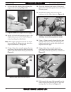
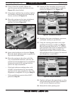
33. Setup a knob indicator as shown in Figure
20, so the knob indicator point is against the
top of the dovetailed table.
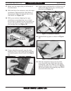
34. Move the carriage to the other end of the
way, read the knob indicator, and note the
amount of total misalignment in parallelism
between the path of the carriage and the
path of the taper attachment.
— If the knob indicator readings show a tilt
of 0.025" or less between the two extreme
positions of the taper attachment, then the
alignmentisacceptable.GotogotoStep 37.
— If the parallelism is greater than 0.025",
proceed to Step 35.
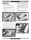
30. Using a 3mm hex wrench, tighten the
cam set screws and the clevis jam nut (see
Figure 16) when finished.
31. Using 8mm and 6mm hex wrenches, tighten
the deadman clamp and the arm clamp cap
screws, as shown in Figure 18.
32. Move the carriage so the taper attachment
stops completely at the forward-most
position, as shown Figure 20.
Figure 20. Taper attachment alignment.
Figure 21. Parallelism correction.
Rotate Slightly
to Align
For Product Mfg. Since 1/10 Model SB1269
-9-
PREPARATION