


24 ► MB656 User Manual
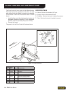
FLOW TEST PROCEDURES
The correct performance of this procedure will verify if
the auxiliary circuit of the carrier is adequate to properly
operate a Stanley attachment.
This procedure is generic in form. It is the end users
responsibility to ensure that this procedure will work with
his specic type of equipment.
If an adequate ow meter is not available contact your
Stanley Hydraulic Distributor for assistance.
TEST PROCEDURE
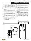
1. With the auxiliary circuit (or kit) completely installed
connect the ow meter between the tool inlet and
outlet hoses.
NOTE:
Always use the hoses that are supplied for the at-
tachment and make sure the machine hydraulic
oil is between 90 to 120 °F. This will assure correct
readings and adjustments.
2. With the machine setting at the mode that’s going to
be used to operate the attachment record the GPM
_____.
Locate the correct ow for the attachment in the
manual under the specication section. Adjust the
machine to the correct GPM.
NOTE:
If possible, always set the machine to the highest
GPM output mode. This will prevent the operator
from over owing the attachments.
3. Once the correct GPM ow is achieved fully open
the restrictor on the ow meter.
4. With the machine in the attachment mode set in
step 2 record the back-pressure. At this point the
pressure reading on the pressure gauge is the back-
pressure in the circuit. This pressure must not ex-
ceed 200 psi/13.5 bar.
Excessive back-pressure will slow the attachments
operation and lead to premature seal failures and
over heating.
Record the back-pressure psi.
5. Close the restrictor valve on the ow meter until the
attachment relief starts to crack or open. The relief
valve opens when the ow rate (GPM), indicated on
the ow meter begins to decline rapidly. Locate the
tools operating system relief pressure in the speci-
cation section in the manual. Adjust attachment re-
lief to specication.
NOTE:
The relief valve pressure must be greater than the
operating pressure of the attachment and three
times the back-pressure. Never use the relief valve
to control the ow rate in the circuit. Cracking pres-
sure means the loss of 4 or more GPM.
Record the relief cracking pressure psi.
Example:
Operation pressure of a breaker is 2700 psi. Back-pres-
sure is 150 psi. A good rule to follow when setting the
relief, multiply the back pressure by 3 then add this num-
ber to the operation pressure of the attachment.
Operating Pressure 2700 psi
Back-pressure 450 psi
Operating pressure of the tool 3150 psi
The relief valve setting must be greater than the estimat-
ed operating pressure of the tool. If the setting is lower,
damage to the circuit may occur. Excess heat will be
generated in the circuit which will damage the attach-
ment and carrier.