


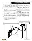


FLOW TEST PROCEDURES
MB656 User Manual ◄ 25
HEAT LOAD TEST
With the installation kit properly installed and adjusted
per the above procedure, conduct the heat load test as
follows.
1. Connect the ow meter between the tool inlet and
outlet hoses.
2. With the carrier set in the attachment mode, re-
strict the ow meter until a pressure of 1000 psi
is achieved. This pressure must be maintained
throughout the heat test.
NOTE:
Closing of the restrictor may be required as the tem-
perature increases.
Monitor the oil temperature from the ow meter until
no change is noted. Record the time required for oil to
stabilize. Record the surrounding temperature (ambi-
ent temperature). Record the time required to stabilize
minutes.
Record the stabilized oil temperature °F.
Record the ambient temperature °F.
The “heat rise” is calculated as the stabilized tempera-
ture minus the ambient temperature.
Example:
Stabilized Temperature 160°
Ambient Temperature -80°
Heat Rise 80°
The normal operating temperature range of this circuit
will be the typical ambient temperature range for the
geographical area plus the heat rise calculated above.
Ensure that the operating temperature range is lower
than 180° for optimum operation of the attachment.
TROUBLESHOOTING
If adequate pump ow is available from the carrier
pump(s) but is not getting to the attachment, consult
your service representative and review the following:
3. Attachment valve(s) are not actuating. Review all
electrical connections that are part of the attach-
ment kit.
4. Ensure proper voltage to the valve(s).
5. Ensure the REG port of the valve is not blocked.
6. Check to make sure the carriers main relief is set
to the manufacturers recommendation and that this
value is equal or greater than the attachment circuit
relief.
7. If the valve will not turn off, check the drain (tank)
line of the valve to ensure that the pressure is 50
psi or less.