


MB656 User Manual ◄ 9
OPERATION
PRE-INSTALLATION INSTRUCTIONS
SKIDSTEER, BACKHOE OR EXCAVATOR
SIZE
Check the Specications section of this manual to de-
termine correct carrier size, hydraulic ow and pressure
requirements.
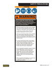
WARNING
If hydraulic pressure, hydraulic back-pressure,
hydraulic ow or carrier weight class are exceeded,
the tool warranty is void.
EXISTING EQUIPMENT HYDRAULICS VS.
APPLICATION ATTACHING KITS
Using existing equipment hydraulic auxiliary systems
for operating hydraulic tools could cause problems for
the hydraulic tool and the hydraulic system if not set up
properly. Simply plugging into the hydraulic system with-
out conrming pressure and ow to the hydraulic tool is
not a good practice. Spare spool valves, dipper circuits,
etc., are just a few examples of easily accessible hy-
draulic circuits which could prove to cause problems for
hydraulic tool usage.
Stanley Hydraulic Tools has for many years developed
ATTACHING KITS for adapting to existing hydraulic sys-
tems of many popular carriers.
If your equipment does not contain an attaching kit, ask
your Stanley dealer for information, installation, and
pricing on a kit which matches your equipment needs.
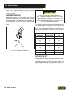
TEST THE HYDRAULIC SYSTEM
1. Have your Stanley dealer test the carrier hydraulic
system to make sure the system is operating at the
manufacturers specied capacity and pressure rat-
ings.
2. Be sure the uid in the hydraulic system is ltered
to at least 10 micro-meters. (Particles found in uid
should not exceed 10 micro-meters in size.)
3. Check the hydraulic lter. Replace the lter if dirty or
deteriorated.
4. Have your Stanley dealer test the circuit to which
the breaker will be connected to make sure that the
circuit is supplying the specied ow and pressure
rating for the breaker. See the Specications section
of this manual.
PRE-OPERATION PROCEDURES
NITROGEN CHARGE
The breaker has been properly charged with nitrogen at
the factory and is ready to use.
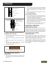
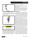
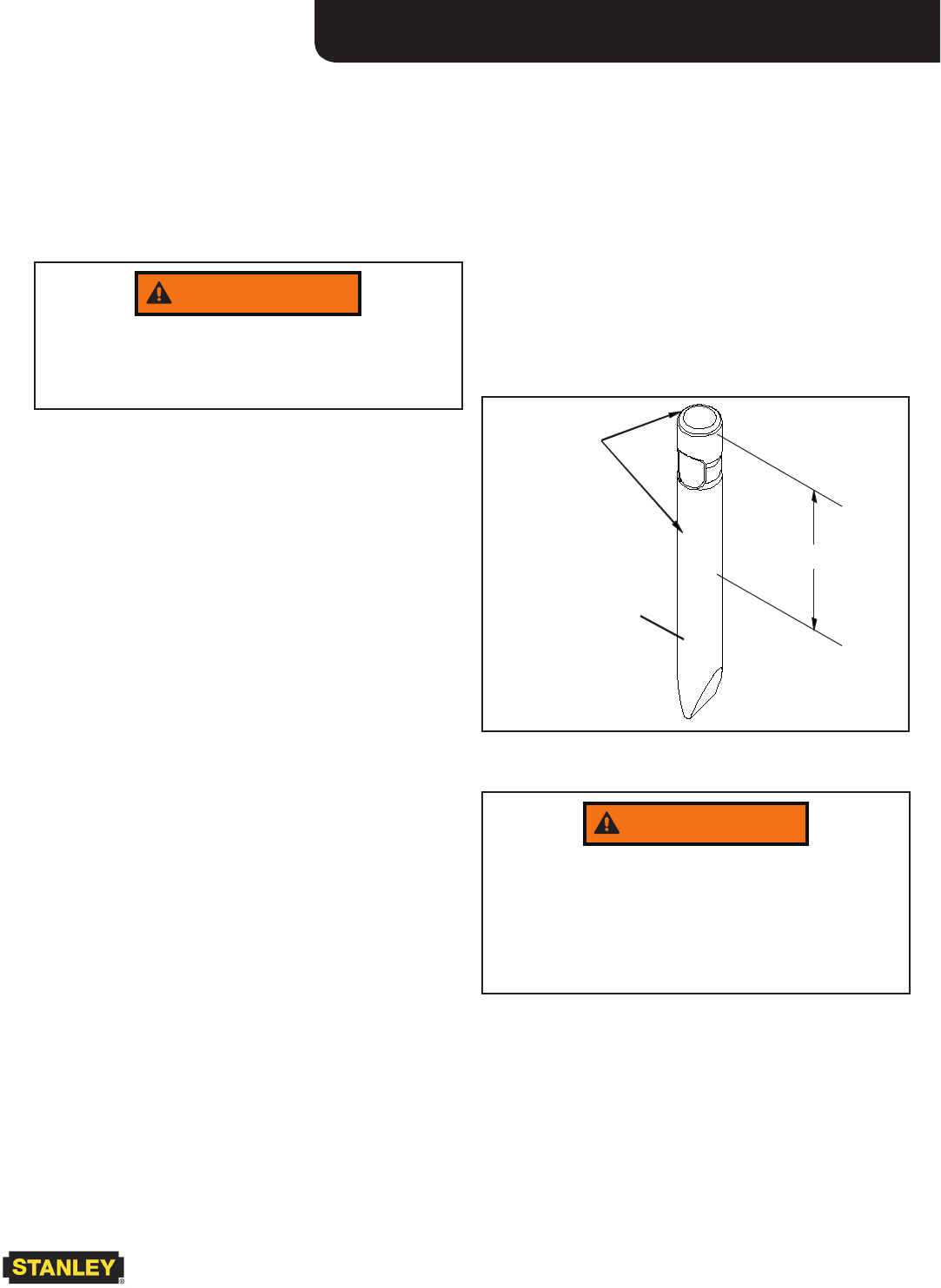
TOOL BIT LUBRICATION
Grease the top 10 in. / 250 mm of the breaker tool bit be-
fore installing. During operation, the tool can be greased
through the grease tting. Grease is required.
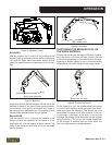
Make sure the tool bit is against the piston by placing the
tool bit against the ground and then putting down pres-
sure on the breaker. See the illustrations below.
250 mm/10 in.
To ol Bi t
Grease
This Area
of Bit
10 inches/250 mm
Figure 1. Greasing the Top of the Tool Bit
WARNING
Greasing the tool bit without down pressure on the
breaker results in grease lling the space between
the piston and the tool bit. When the breaker is next
activated, the piston will strike the grease at a speed
which will pressurize the grease resulting in seal and
grease zerk failure.