


10 ► FG10/PG05 Service Manual
OPERATION
3. Using the wrench (127) provided, place it on the
ats of the drive ange. Place a strap wrench on
the grinding wheel and then tighten by gripping and
turning the strap wrench while holding the wrench
provided.
4. Replace the guard weldment.
WHEEL PIVOT ADJUSTMENTS
FOR PROFILE OR FROG GRINDING
OPERATIONS
NOTE: The PG05 does not contain the pivot wheels
or the extension assembly.
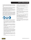
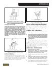
GRINDING WINGS
For grinding a wing of the frog, place the grinder on top
of the wing with the rollers (91) resting on top of the wing
to be ground. Adjust each wheel pivot (86) to the posi-
tion shown in gure 1. Grinding is accomplished by mov-
ing the grinder back and forth in line with the rail. When
nished with one wing, rotate the entire grinder 180 de-
grees and place it on the other wing.
PREOPERATION PROCEDURES
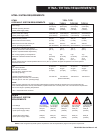
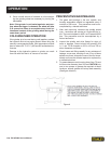
CHECK HYDRAULIC POWER SOURCE
1. Using a calibrated owmeter and pressure gauge,
check that the hydraulic power source develops a
ow of 7-10 gpm/26-38 lpm at 1500-2000 psi/105-
140 bar.
2. Make certain the hydraulic power source is equipped
with a relief valve set to open at 2100-2250 psi/145-
155 bar minimum.
3. Check that the hydraulic circuit matches the tool for
open-center (OC) or closed-center (CC) operation.
CHECK TOOL
1. Make sure all tool accessories are correctly in-
stalled. Failure to install tool accessories properly
can result in damage to the tool or personal injury.
2. There should be no signs of leaks.
3. The tool should be clean, with all ttings and fasten-
ers tight.
CHECK TRIGGER MECHANISM
1. Check that the trigger operates smoothly and is free
to travel between the “ON” and “OFF” positions.
CHECK GUARD WELDMENT
1. Inspect the wheel guard weldment for cracks and
other structural damage.
INSTALLING AND REMOVING
GRINDING WHEEL
NOTE: Use 6 inch diameter up to 3 inch thick (Type
6 for USA) grinding wheels with a 5/8-11 threaded
arbor hole. Only use grinding wheels which comply
with ANSI B7.1, B7.5/ISO 525, 603.
READ AND BECOME FAMILIAR WITH THE SEC-
TIONS IN THIS MANUAL ON SAFETY PRECAU-
TIONS, TOOL STICKERS AND TAGS, HYDRAULIC
HOSE REQUIREMENTS, HYDRAULIC REQUIRE-
MENTS, AND PREOPERATION PROCEDURES BE-
FORE USING THIS PRODUCT.
USA CONFIGURATION
1. Unscrew the two nuts (98) which secure the guard
weldment (95) to the frame and remove the guard
weldment.
2. Install the grinding wheel until it comes in contact
with the drive ange.
IMPORTANT
Never over-tighten the grinding wheel by impacting
the wrench with a mallet or hammer. Sufcient
torque is attained by hand-tightening the wheel with
a strap wrench while securing the drive ange with
the wrench provided.