


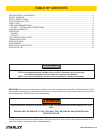

RS25 User Manual ◄ 11
PRE-OPERATION PROCEDURES
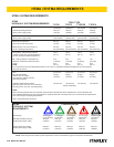
CHECK HYDRAULIC POWER SOURCE
1. Using a calibrated owmeter and pressure gauge,
check that the hydraulic power source develops a
ow of 9–10.5 gpm/34–40 lpm at 2000 psi/140 bar.
2. Make certain the hydraulic power source is equipped
with a relief valve set to open at 2200–2300 psi/152–
159 bar minimum.
3. Check that the hydraulic circuit matches the tool for
open-center (OC) operation.
CHECK TOOL
1. Make sure all tool accessories are correctly in-
stalled. Failure to install tool accessories properly
can result in damage to the tool or personal injury.
2. There should be no signs of leaks.
3. The tool should be clean, with all ttings and fasten-
ers tight.
CHECK TRIGGER MECHANISM
1. Check that the trigger operates smoothly and is free
to travel between the ON and OFF positions.
CHECK GUARD ASSEMBLY
1. Inspect the wheel guard assembly for cracks and
other structural damage.
INSTALLING AND REMOVING
ABRASIVE CUTTING WHEELS
NOTE:
Use 14 in./350 mm diameter (for 14 in. model) or 16
in./400 mm diameter (for 16 in. model) abrasive cut-
ting wheels with a 1 in. arbor hole. Only use cutting
wheels which comply with ANSI B7.5/ISO 525, 603.
Make sure the paper labels or blotters are installed
between the wheel and collars.
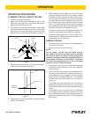
1. Before installing abrasive wheels, “sound” the wheel
for possible damage by hanging the wheel vertically
be the arbor hole and rapping lightly with a screw-
driver handle or similar instrument. Thin, organic
bond wheels will produce a low drumming tone if it
is physically sound. If the wheel produces a “dead”
or “at” sound, it may be cracked. Cracked or dam-
aged wheels must never be used.
2. Check that the surfaces of the wheel that come in
contact with blotters and anges are free of dirt and
other foreign particles.
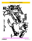
3. Remove the jam nut (77) and outside collar (78) by
using a box type wrench while gripping the cutting
wheel.
4. Install the cutting wheel. Make sure blotters or labels
remain on the cutting wheel.
5. Reinstall the outside collar and jam nut. Tighten the
jam nut with a box type wrench while gripping the
cutting wheel. Only tighten sufciently to prevent
slippage of the wheel between the collars (78 & 79).
DRIVE SHAFT SPEED CHECK
The speed of the motor output shaft should be checked
at least every 100 hours of operation by trained and
experienced personnel. A record of the speed checks
should be maintained. The rated speed of the RS25 Rail
Saw is 3600 rpm at 10 gpm/38 lpm for the 16 inch/400
mm model and 4500 rpm at 10 gpm/38 lpm for the 14
inch/350 mm model. The cutting wheel must be rated for
a minimum of 4700 rpm for the 16 inch/400 mm mod-
el and 5300 rpm for the 14 inch/350 mm model. Tests
should be conducted while operating the normal power
supply used with the saw.
CONNECT HOSES
1. Wipe all hose couplers with a clean lint-free cloth
before making connections.
2. Connect the hoses from the hydraulic power source
to the hose couplers on the rail saw. It is a good
practice to connect the return hose rst and discon-
nect it last to minimize or avoid trapped pressure
within the rail saw motor.
3. Observe ow indicators stamped on hose couplers
to be sure that oil will ow in the proper direction.
The female coupler is the inlet coupler.
NOTE:
The pressure increase in uncoupled hoses left in the
sun may result in making them difcult to connect.
When possible, connect the free ends of operating
hoses together.
OPERATION