


10
SPINDLE LOCK
WARNING: To prevent accidental operation,
turn off and unplug tool before performing the
following operations. Failure to do this could result
in serious personal injury.
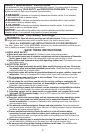
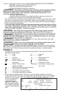
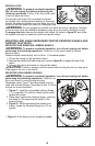
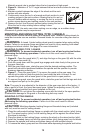
Thespindlelockbutton(6)isprovidedtoprevent
the spindle from rotating when installing or removing
wheels. Operate the spindle lock only when the tool is
turned off and the wheel has come to a complete stop.
WARNING: Do not engage the spindle lock while the tool is operating. Damage
to the tool will result and attached accessory may spin off possibly resulting in injury.
To engage the lock,depressthespindlelockbutton(6)showninfigure E1 and rotate
the spindle until you are unable to rotate the spindle further.
MOUNTING AND USING DEPRESSED CENTER GRINDING WHEELS AND
SANDING FLAP DISCS
MOUNTING AND REMOVING HUBBED WHEELS
WARNING: To prevent accidental operation, turn off and unplug tool before
performing the following operations. Failure to do this could result in serious
personal injury.
Hubbed wheels install directly on the 5/8 in.-11 threaded spindle.
1. Thread the wheel on the spindle by hand.
2.Depressthespindlelockbuttonanduseawrench(figure E1)totightenthehubofthe
wheel.
3.Reversetheaboveproceduretoremovethewheel.
CAUTION: Failure to properly seat the wheel before turning the tool on may result
in damage to the tool or the wheel.
MOUNTING NON-HUBBED WHEELS
WARNING: To prevent accidental operation, turn off and unplug tool before
performing the following operations. Failure to do
this could result in serious personal injury.
DepressedcenterType27grindingwheelsmustbe
usedwithincludedflanges.Seepages9and10ofthis
manual for more information.
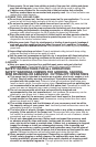
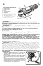
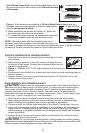
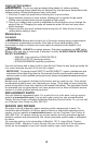
1. Figure F - Install the unthreaded backing flange
(11)onspindle(12)withtheraisedsection(pilot)
against the wheel.
2.Placewheelagainstthebackingflange,centering
thewheelontheraisedsection(pilot)ofthe
backing flange.
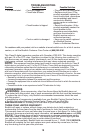
3.Figure G - While depressing the spindle lock
button,threadthethreadedclampnut(13)on
spindle.
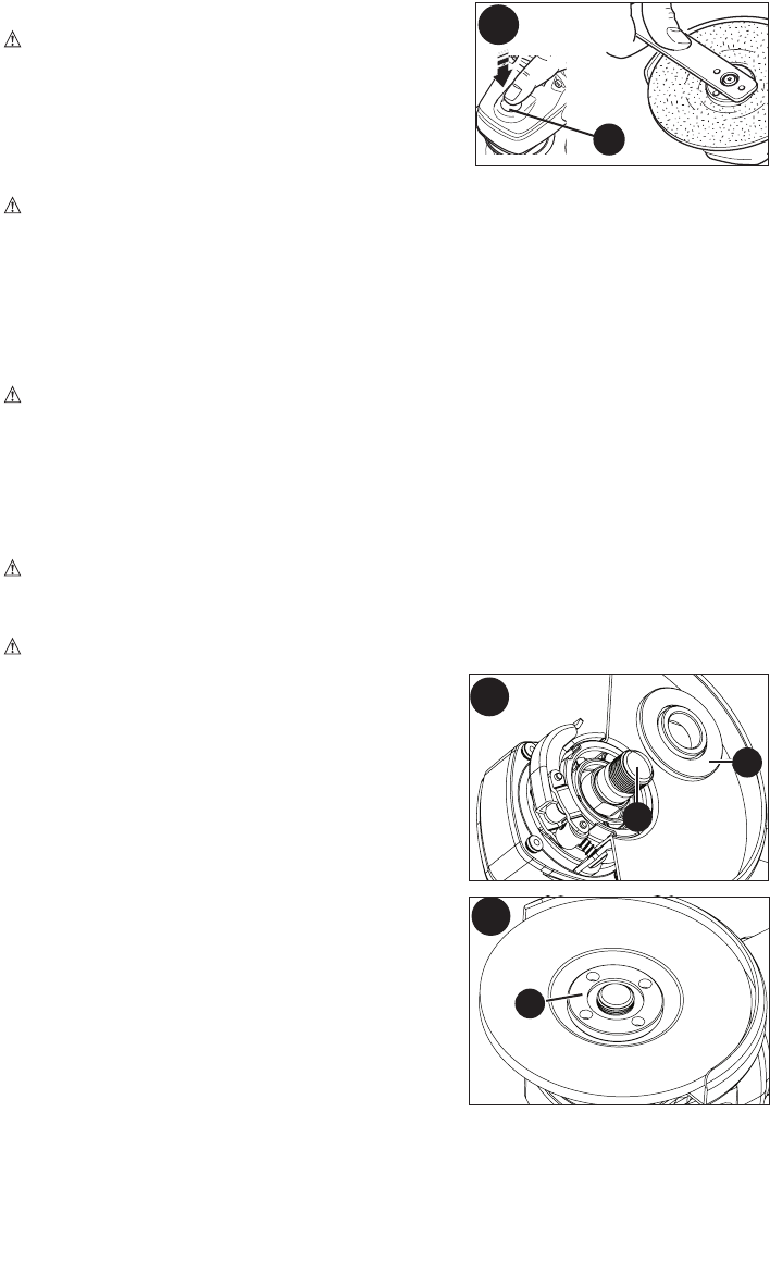
•Figure H - If the wheel you are installing is more
F
11
12
E1
6
G
13