7
Assembly
WARNING:
To prevent accidental operation, turn off and unplug tool before
performing the following operations. Failure to do this could result in serious personal injury.
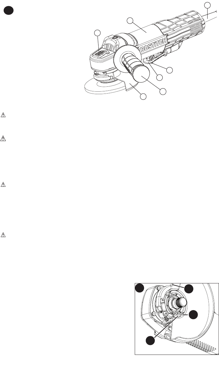
AUXILIARY HANDLE
WARNING:ThishandleSHOULDBEUSEDATALLTIMEStomaintaincomplete
control of the tool.
Anauxiliary3positionhandleisfurnishedwithyourgrinder.Itcanbescrewedinto
either side or the top of the gear case housing.
Accessories
It is important to choose the correct guards, backing pads and flanges to use with
grinderaccessories.Seepage9forinformationonchoosingthecorrectaccessories.
CAUTION: Accessories must be rated for at least the speed recom mended on the
tool WARNING label. Wheels and other accessories running over their rated
accessory speed may fly apart and cause injury. Threaded accessories must have a 5/8
inch-11hub.Everyunthreadedaccessorymusthavea7/8inch(22mm)arborhole.Ifit
does not, it may have been designed for a circular saw. Use only the accessories shown
onpage9ofthismanual.Accessoryratingsmustalwaysbeabovetoolspeedasshown
on tool nameplate.
MOUNTING GUARD (FIGURES B & C)
CAUTION: Guards must be used with all grinding wheels, sanding flap discs,
wire brushes cut-off wheels and wire wheels. The tool may be used without a guard
onlywhensandingwithconventionalsandingdiscs.TheBTE820isprovidedwithaguard
intendedforusewithdepressedcenterwheels(Type27)andhubbedgrindingwheels
(Type27).Thesameguardisdesignedforusewithsandingflapdiscs(Type27and29)
andwirecupbrushes.GrindingandcuttingwithwheelsotherthanType27and29require
different accessory guards. A Type 1 guard is provided for use with a Type 1 wheel.
Both Type 27 and Type 1 guards attach and are removed in the same way as
described below.
1. Figure B-Opentheguardlatch(7),andalignthe
lugsontheguard(8)withtheslotsonthegear
casecover(9).
2.Pushtheguarddownuntiltheguardlugsengage
and rotate freely in the groove on the gear case
hub.
3.Withtheguardlatchopen,rotatetheguardintothe
desired working position. The guard body should be
positioned between the spindle and the operator to
provide maximum operator protection.
1
4
5
3
2
6
A
FUNCTIONAL DESCRIPTION
1. Paddle switch
1a. Lock off lever
2.Cord
3.Toolfreeguard
4.Bodygrip
5.Auxiliaryhandle(3positions)
6.Spindlelockbutton
7.Guard(Type27orType1if
soequipped)(notshown)
1a
B
9
8
7


