


Additive Feeders Chapter 4: Operation 26 of 50
Extruder Tracking Control
The extruder tracking control option allows the additive feeder’s auger (follower) to turn in a
precise ratio to the speed of your extruder screw (master). The speed control on the feeder
can be set for any feed ratio from 1% to 999.9%.
The extruder tracking control detects the speed of the extruder screw and causes the feeder
screw to rotate at the desired RPM. In effect, the extruder tracking control acts as an
automatic speed control.
The extruder tracking control requires a 5 VDC TTL NPN RPM signal from the extruder.
Use an existing RPM signal from the extruder; consult with the extruder’s manufacturer for
the signal type and frequency.
You will need to know:
1. The signal voltage
2. The number of pulses per extruder screw revolution
A wide variety of sensors can be supplied by the manufacturer to suit your needs if the
extruder control circuit does not provide a suitable signal.
These sensors include:
• Inductive proximity sensors to sense gear teeth.
• Magnetic pickups to sense affixed magnets.
• Optic sensors to sense affixed reflective tape.
Consult your sales representative for additional information.
Extruder Tracking Installation and Setup
The additive feeder control is supplied with standard factory defaults. Control programming
is required to suit the requirements of your process.
Connect the TTL signal acquired from the extruder control or from a sensor you have
installed to the terminal strip as shown in the electrical schematics provided with your unit’s
installation packet.
1. Install the feeder as described in Chapter 3.
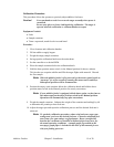
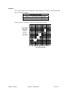
2. Calibrate the feeder as described on Page 20. Determine the feed rates at different
rpms. We recommend that you plot the feed rates on graph paper.
3. Calculate a new display constant taking the extruder screw signal into account.
Constant = 1000 x # of Pulses per Revolution of Extruder Screw ➀
# of Pulses per Revolution of the Feeder Screw ➁
➀ If not counted directly from screw, multiply by a “fudge factor” to get the pulses per extruder
screw rpm.
➁
Factory set at 50.4 (PPR x 25.2 gear ratio).
4. Program the control to the new constant, as described in the next section “Field
Control Programming.”
5. Change DIP switch #5 to ON.