


Additive Feeders Chapter 4: Operation 30 of 50
Viewing or Changing the Program Minimum Setting
1. Enter the programming mode, then flip DIP switch 2, Program Minimum Setting,
to ON.
2. The current value for the lower limit FACTORY SETTING = 0 will appear in the
LED display.
3. Use the Up or Down buttons to change the lower limit, as desired.
4. When finished, flip DIP switch 2 to OFF.
5. The display should read PROG.
Viewing or Changing the Program Maximum Setting
1. Enter the programming mode, then flip DIP switch 3, PROGRAM MAXIMUM
SETTING to ON.
2. The current value for the upper limit FACTORY SETTING = 70 will appear in the
LED display.
3. Use the Up or Down buttons to change the upper limit, as desired.
4. When finished, flip DIP switch 3 to OFF.
5. The display should read PROG.
Exiting Programming Mode and Returning to Run Mode
1. Make sure DIP switches 4, TIME/RATE MODE SELECT, and 5,
MASTER/FOLLOWER MODE SELECT are in the desired positions factory
Setting 4 = 1, 5 = OFF, ON FOR OPTIONAL EXTRUDER TRACKER
CONTROLS BEFORE entering the RUN mode (DIP switch 7 OFF).
2. Make sure DIP switches 1 through 4 are OFF.
3. If satisfied with the programmed values, flip DIP switch 7 to OFF.
4. Control should begin to operate normally, using the values and modes selected.
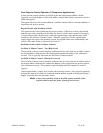
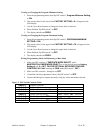
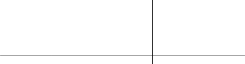
Figure 3: DIP Switch Function Table
Switch 1
Program Constant
Switch 2
Program Minimum Setting
Switch 3
Program Maximum Setting
Switch 4
Decimal Select
0 – 4 = Decimal Points
Switch 5
Master/Follower Select
OFF = Master ON = Follower
Switch 6
Do Not Use – Set to OFF
Switch 7
Program/Run Select
OFF = Run ON = Program
Switch 8
Do Not Use – Set to OFF