


-9-
D.3 Cabling / wiring
When making connections to the unit you must ensure that all connections
are carried out in a clean and correct manner and under no circumstances that a
cable is connected to a wrong terminal.
Connecting the unit must be carried out in the following order.
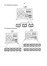
D.3.1 Connection to battery
Prepare the batteries for connection. Prepare battery cables, if necessary press
on cable tabs/shoes. Connect the red cable to the Battery positive fuse/circuit
breaker and the black cable to battery Minus (-) Take care when connecting the
second cable to the battery, as a spark is produced, this is caused for a short time
due to high current flowing in the unit to charge the capacitors. This is another
reason to install a battery fuse/circuit breaker. For this reason follow strictly the
safety measures described in this manual.
DO NOT INSERT THE BATTERY FUSE AT THIS STAGE.
D.3.2 Connection to the AC OUTPUT.
The AC output must be connected to the screw terminal AC OUTPUT. For this,
use a 3-core cable with a conductor cross section of 2,5mm². Connections are
marked as follows “OUT / N”=Neutral, “GND”=Earth, “OUT / L”=Live or Active.
Caution: High voltage can be at the AC output, ensure the unit is not
connected when making AC connections.
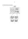
D.3.3 Connection to the AC INPUT
The AC input supply from the electricity grid or from a generator must be
connected to the screw terminals AC INPUT. For this use a 3-core cable with a
conductor cross section of 2,5mm². Connections are marked as follows
“IN / N”=Neutral, “GND”=Earth, “IN / L”=Live or Active.