


-20-
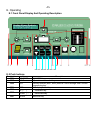
G.2 The Transfer system
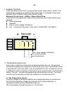
When an AC voltage is present at the AC IN of the unit , the “AC IN” LED is lit.
When this voltage matches the Parameter P-06 value set, and the frequency is
between 44Hz and 65Hz, then this power is transferred directly to the AC load and
the battery charger section . The “TRANSFER” LED is lit to indicate
this has happened. The inverter is then switched off and the battery charger
switched on. This process is automatic and should not be noticed by the load, at
worst a slight flicker may be seen in lights.
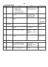
The maximum current of the Bypass switch is 60A (CUxx3500) resp.
30A (CUxx1700). That means through this system AC loads of up to a
maximum of 7000 W (CUxx3500) or 3500W (CUxx1700) can be operated.
When the Battery Charger is working, part of this power is used for the charging
according to the power sharing settings.
The Transfer system is protected against overload with an automatic breaker
on the AC Input side of the unit . If the system has been overloaded
the Input breaker will pop-out. To put the automatic safety system back in
to operating you must push this breaker for reset.
Note: In inverter operation the unit generates a pure sinewave and quartz
stabilized output voltage. However, when the unit is transferring power from
the grid or a generator the voltage and quality of the power running the AC load
will be the same as that coming from the grid or generator. The unit cannot
modify the incoming AC supply.
G.3 The solar charge regulator
The unit has a built-in solar charge regulator. To charge the batteries
solar modules can be connected to the terminal SOLAR IN +/-. The
built-in regulator is a shunt regulator with a maximum input current of 30A for all
series products. The operating voltage of solar modules to be connected must
match the actual operating voltage of the unit and never exceed the max. rated
value.
Under no circumstances should any other charging sources such as a
wind-generator be connected at the input of the solar charge regulator.
The Solar Charge Regulator works automatically and is always in operation. As
soon as the energy is delivered from the solar charge regulator, the “SOLAR
CHARGE” LED is lit and the batteries are being charged, The solar charge
regulator works even when the battery charger is functioning. The method of
operation is a 3 or 4 step charging process, the same as the battery charger. The
function is described in the section on battery charger. The programming and the
adjustments are carried out in accordance with the section on battery charger.
The programming and the adjustments are carried out in accordance with the
same conditions. Check with your battery supplier which adjustments must be
carried out for your battery.