


Combi 650
-11-
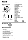
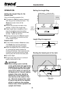
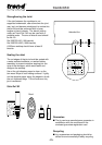
■ Insert both location bushes into Red dot
holes. Red dot face uppermost.
■ Lay jig across the worktop, ensure the
location bushes touch the postform edge.
Clamp jig in position with quick action clamps.
Draw a line 8.5mm away from the jig slot
edge.
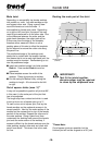
■ With the mitred end of the length stop facing
towards the back of the worktop, as shown.
Fit the length stop onto underside of jig by
using the countersunk bolt, washer and knob
into one of the holes in the jig. The bolt
should be put into the jig from above, do not
tighten. Carefully position the point of the
length stop so that it lines up with the 8.5mm
margin pencil line. When the correct position
has been obtained tighten bolt and knob
sufficiently to prevent length stop from
moving.
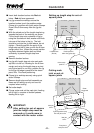
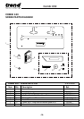
■ Remove location bushes.
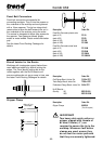
■ Lay jig with length stop set onto male work
top that is to be cut. Allowing for the 8.5mm
margin and using the length stop as a pivot
point (pivot point on cut line), position the jig
so the jig slot edge is parallel to the drawn
pencil line. Re-check positioning.
■ Clamp jig to worktop securely using quick
action clamps.
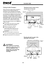
■ Remove length stop and bolt assembly as
these are for setting up only and are not
required when routing.
■ Set cutter depth.
■ Plunge router and cut the male joint, feeding
left to right in a series of shallow passes,
feeding left to right.
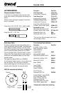
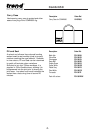
Cutting male
joint on out-of-
square joints
Direction of
router travel
Postform edge
Quick action
clamp here
Shown
exaggerated
Male joint
cut line
Direction of
router travel
Postform edge
Quick action
clamp here
Setting up length stop for out-of-
square joints
Location bushes
(Red dot)
Parallel pencil line
8.5mm from jig slot edge
IMPORTANT!
After setting for out-of-square
joint the length stop must be
removed or it could come in
contact with the router cutter.
8.5mm margin
pencil line
Male joint
cut line
Pivot point on
male joint cut line
Jig slot edge 8.5mm away
from male joint cut line