


Combi 650
-8-
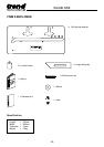
ASSEMBLY
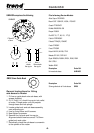
Location Bush Identification
Two location bushes are used in different holes
in the jig to align the correct template aperture
for the application.
The holes are colour coded for easy
identification with dots as follows:
Green dot – Female Joint
Red dot – Male Joint
Yellow dot – Connector Recess
The jig has a colour coded key on its label for
quick reference.
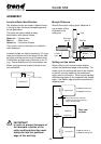
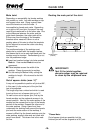
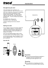
Setting out the Joints
When cutting a joint ensure location bushes
contact the postformed edge of the worktop. For
certain joints the worktop will need to be inverted
so that all cuts are made into the postformed
edge, never out through it. When routing worktop
the balancing paper on the underside may feather
edge – this feather edge should be removed with
abrasive paper.
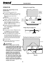
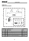
Location bushes are held in position by ‘O’ rings.
Insert the smallest end of the bush into the hole
by lightly pushing and turning at the same time.
If the bushes are tight use a lubricant on the ‘O’
ring. Ensure bushes are fully home before use.
When using jig ensure location bushes do not
foul workbench.
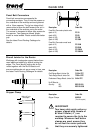
23mm
IMPORTANT!
In order to prevent breakout of
the laminate, rotation of the
cutter and feed direction must
always be into the postform
edge of the worktop.
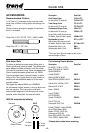
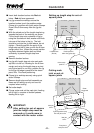
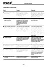
Margin Distance
Allow 8.5mm when cutting joints. Measure or
use a batten of this
thickness to aid
setting out.
Plan view
of joints
O ring
Location bush
Cutter
Sub base
Guide bush
30mm Ø
Location
bush
Worktop
Template
8.5mm
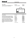
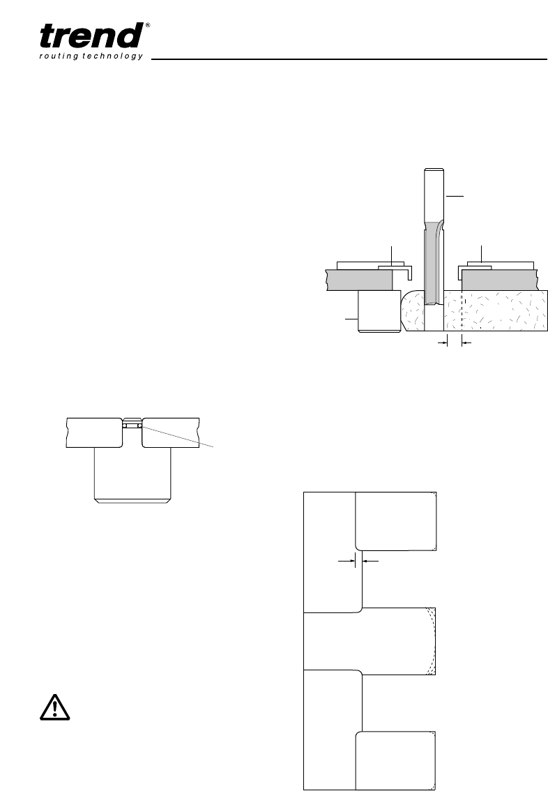
Right hand joint
Male
Female
Male
Female
Cut male with laminate down
Cut female with laminate up
Postform edge
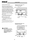
The joint takes up 23mm, this should
be allowed for with extra material in the
length of the male worktop.
Male
Female
Postform edge
PENINSULA
Postform edge
Postform edge
Male
Female
Left hand joint
Cut male with laminate up
Cut female with laminate down