


TABLE OF CONTENTS
SECTION I DESIGN
For The System Design Engineer Page
1. Introduction................................................................................................................................ 1
2. General Description................................................................................................................... 1
3. System Design and Layout........................................................................................................ 2
SECTION II INSTALLATION
For The Installing Contractor
1. Unpack and Inspect ................................................................................................................... 3
2. Position Air Cleaner Cabinet..................................................................................................... 3
3. Connect Adjoining Ductwork .................................................................................................... 3
4. Mount Detergent System ........................................................................................................... 3
5. Connect Drain............................................................................................................................. 3
6. Connect Wash Water Supply..................................................................................................... 3
7. Mount Control............................................................................................................................. 4
8. Complete Wiring
A. High Voltage Wiring................................................................................................................ 4
B. Primary Wiring........................................................................................................................ 4
9. Fire Suppression System (when factory supplied).................................................................. 4
10. Checkout for System Start-up .................................................................................................. 4
SECTION III OPERATION AND SERVICE
For The Maintenance Engineer
1. Introduction and Principle of Operation................................................................................... 5
2. Initial Start-up............................................................................................................................. 6
3. Wash Control and Detergent System Settings......................................................................... 8
4. Routine Maintenance ................................................................................................................. 9
5. Preventative Maintenance ......................................................................................................... 9
SECTION IV TROUBLESHOOTING
For The Maintenance Engineer
1. Trouble Shooting ..................................................................................................................... 11
2. Spare Parts............................................................................................................................... 12
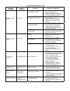
3. Trouble Reference Chart ......................................................................................................... 13
SECTION V REFERENCE
Illustrations and Drawings
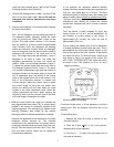
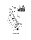
Figure 1 General Component Arrangement...................................................... 14
Figure 2 Unit Outline .......................................................................................... 15
Figure 3 Control Outline..................................................................................... 16
Figure 4 Detergent System Outline................................................................... 17
Figure 5 Piping Schematic................................................................................. 18
Figure 6 Field Wiring Diagram........................................................................... 19
Figure 6a Second Wash Section Field Wiring Diagram................................... 19a
Figure 7 Fire Control System Outline................................................................ 20
Figure 8 ATS Control Schematic Page 1........................................................... 21
Figure 9 ATS Control Schematic Page 2........................................................... 22
Figure 10 AIR BOSS Control Schematic Page 1................................................. 23
Figure 11 AIR BOSS Control Schematic Page 2................................................. 24
Figure 12 ATS Remote Box Schematic Page 1................................................... 25
Figure 13 ATS Remote Box Schematic Page 2................................................... 26
Figure 14 Standard Single Section Sequence Timing ....................................... 27