5
SECTION III OPERATION
WARNING
RISK OF ELECTRIC SHOCK
These servicing instructions are for use by qualified
personnel only. To reduce the risk of electric shock,
do not perform any servicing other than that
contained in the operating instructions unless you
are qualified to do so.
FOR THE MAINTENANCE ENGINEER
1. Description and Principles of Operation
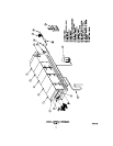
The basic ATS units are made up of five modular
sections. Each of the first three sections employs
different mechanisms to remove and capture particulate
matter from the air.
The first section, an impinger, is primarily designed for,
and is especially effective in, capturing relatively large
greasy liquid particulate. The impinger is constructed of
two equally spaced layers of roll formed baffles. The
spacing creates and air flow pattern which causes the
contaminate to collect and flow down the baffles. Holes
in the frame permit the liquid to drip into the drain basin
below. Periodically, at a predetermined setting a
remotely located control automatically activates
oscillating wash manifolds located on both sides of the
impinger to flush away any remaining tenacious matter.
(Refer to the electronic air cleaner section below for
additional description on the integral washer. It is
identical to the impinger washer.)
The second section houses an electronic air cleaner,
technically known as an electrostatic precipitator. In this
type of equipment, all airborne particles, even of
microscopic size, are electrically charged (positively) as
they pass through a high voltage ionizer. These charged
particles are then attracted and adhere to a series of
parallel collecting plates, which form the negative
elements of an electrostatic field.
The ionizer consists of charged stainless steel spiked
blades spaced between grounded electrodes. The
collecting section consists of parallel plates arranged so
that each alternate plate is charged while the
intermediate plates are electrically grounded.
The ionizing-collecting cells (contaminate collecting
elements) are housed in the cabinet on slide rails. They
can be removed from the cabinet as required, through
the end access door, by sliding them out like drawers.
On multicell units, all of the electrical connections
between cells in a given tier are automatically made
through spring connectors. On the access end, the high
voltage from the power pack(s) is made with cables.
When installing cells into the cabinet, observe the
directional arrows on the cell end plates. The side of the
cell containing the spiked ionizer blades always must be
located on the air entering side.
The power supply(s) convert the 115-volt, 60Hz, single-
phase AC supply to the high voltage DC needed to
power the cell(s). The power supplies are solid state,
pulse width modulated (PWM), line and load regulated.
Potential output voltages of 12.5 KVDC are required for
the ionizer and 6.25 KVDC for the collector at a
maximum current of 6 MA. Each supply is retained in
the control in slide channels and secured with one bolt
located in the top corner of the circuit board.
At a predetermined frequency the remotely located
control automatically activates an integral wash system
to flush away the collected contaminant. When
activated, the duration of the washing cycle is
approximately 80 minutes.
The wash system consists of a series of spray nozzles
soldered into oscillating water wash manifolds. The
manifolds are located in the front and rear of each cell
tier. They are mechanically interconnected with a drive-
belt and driven through direct linkage by a fractional HP
motor. A detergent feeder is also incorporated into the
wash system. The amount of detergent needed for each
wash is readily field adjustable and that amount is
dependent upon wash water temperature, the type and
amount of contaminant collected.
In addition to the preset automatic wash cycle, the
washing operation may be initiated manually when
required. The events in a wash cycle are:
A. Power pack(s) and system blower ”OFF”
B. Washer and detergent “ON” (each module)
C. Washer and detergent “OFF” (each module)
D. Pause for detergent to react
E. Washer “ON” for rinse (each module)
F. Washer “OFF” (each module)
G. Blower “ON” for forced dry
H. Power pack(s) “ON”
When a fire control system is specified, both the
impinger and electronic air cleaner sections contain
chemical spray nozzles.
The third section houses a bag filter(s). In the event of
an electrical outage in the electronic air cleaner, the bag
filter acts as a safety backup collector.
Also, in some applications, the bag filter will collect any
precipitated agglomerates that may tend to “blow-off”
the electronic air cleaner.
When the bags become saturated with contaminant
they must be removed and replaced. However, this
requirement is relatively infrequent due to the pre-
filtration upstream from the bag.


