


1
SECTION I DESIGN
FOR THE SYSTEM DESIGN ENGINEER
1. Introduction
ATS units are Air Treatment Systems designed to
efficiently remove a variety of contaminants from an air
stream. These contaminants my range from those found
in normal kitchen ventilation air to weld fumes or oils
and effluents from various manufacturing processes. A
range of units is available to clean specific air volumes.
Each unit is made up of mechanical and electronic “dirt”
collecting modules and efficient, trouble free operation
is absolutely dependent upon the periodic removal of
the collected contaminate from the cleaning elements.
Unit design simplifies this requirement.
When properly installed, operated and maintained, the
ATS unit will effectively and efficiently perform its
designed task.
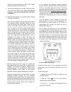
2. General Description
The standard major components supplied with each
ATS unit are as follows:
• Base unit consisting of five modular sections: 1)
impinger, 2) electronic air cleaner 3) bag type media
filter 4) activated carbon adsorber and 5)
blower/motor.
• Washer control including high voltage power
supply(s) to be mounted remotely.
• Detergent system to be located remotely.
• Wash water supply-line strainer.
The impinger section contains impinger panels to collect
grease and liquid particulate, oscillating front and rear
wash manifolds and metal mesh pre-filters (and after-
filter when specified).
The electronic air cleaner section contains the ionizing-
collecting cells to remove very fine particles; oscillating
front and rear wash manifolds and metal mesh pre-
filters and after-filters.
When a factory installed fire suppression system is
specified, both the impinger and electronic air cleaner
sections include spray nozzles. Fire control is usually
required in kitchen exhaust and similar applications.
The media section contains bag type filters providing
safety filtration for the electronic air cleaner in the event
of any accumulated blow-off or contaminant penetration
in the event of an electrical outage.
For odor control, the adsorber section contains the
activated carbon panels in a vee bank configuration.
With the exception of the wash manifolds and the
blower/motor, all the major components slide in and out
of the housing for ease of service.
To provide access to the system components (except
the blower section), gasketed doors with push-button
latches and lift-off hinges are located 90 degrees to the
direction of airflow on one side of the cabinet. Access
preference should be noted when unit is ordered.
Access to the blower section is obtained by removing
the bolts retaining the discharge end panel.
The power supplies providing the necessary high
voltage for the electronic air cleaner and the controls
initiating and sequencing the wash cycle are housed in
a NEMA 12 enclosure designed for remote mounting. In
addition, the enclosure is a central junction for the
primary wiring.
The standard 16-gallon detergent system is furnished
as a completely assembled unit to be piped directly to
the wash water supply, into the wash manifold headers.
Note: 30 or 55-gallon detergent tanks are available as
an option.
Note: Trion Tridex Detergent is specially formulated for
use with Trion electronic air cleaners. Use of other
cleaners and detergents, not specifically approved by
Trion, can cause possible failures in the unit and will void
any warranties on our equipment.
The strainer is to be installed in the wash water supply
line. Factory installed solenoid valves are located in the
piping inside the impinger and the electronic air cleaner
sections.
An optional chemical fire suppression system may be
specified to be included with the ATS unit if it is a
requirement of the application. The system available
from the factory must be completed at the
installation site by a qualified and authorized fire
control contractor. In addition to final hook-up, he will
complete tie-in with other existing systems, test, final
inspect and if necessary, coordinate his work with local
or other designated fire inspectors. The fire suppression
system includes strategically located, spray nozzles and
an electrical fire detection device to signal a control
head that opens a valve to discharge a chemical
cylinder. An auxiliary mechanical “Pull” is also supplied
to be installed at a remote location to manually activate
the system. The general contractor should coordinate
his work with that required by the fire control contractor.
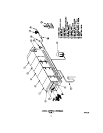
Refer to fire control system outline drawing, Figure 7.
The following are standard options that may be
specified on the basic systems:
1. Without carbon section
2. Without media section*
3. Without carbon and media sections
4. Without blower section
5. Additional electronic air cleaner section (double
pass unit)
6. 30 or 55 gallon detergent system
7. Perforated plate in lieu of the metal mesh filters
8. Fire suppression system