


4
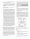
7. Mount Control
Mount the wash control, also containing the high voltage
power supplies, in the selected location. It must be
mounted indoors out of the weather and should be at
eye level to ease in monitoring unit operation and as
close to the ATS unit as practical. Allow sufficient space
in front of the access door for service. Refer to Figure 3
for mounting hole layout and dimensions.
8. Complete Wiring
(a). High Voltage Wiring
WARNING:
EXERCISE ALL THE NORMAL PRECAUTIONS
WHEN WORKING WITH HIGH VOLTAGE AND
COMPLY WITH NEC AND ALL APPROPRIATE
LOCAL CODES.
The high voltage wiring entails interconnecting the
power supply(s) with the ionizing-collecting cell(s)
located in the electronic air cleaner section cabinet.
On multicell units, the wiring between the cells
within a tier is automatically made with intercell
spring contacts.
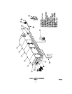
Refer to the Field Wiring Diagram Figure 6. Two 50
ft., (or the length specified) high voltage leads, one
for the ionizer and one for the collector, are factory
furnished. When the installation requires more than
one power supply, a set on leads is furnished for
each supply. Ring type connectors have been
factory installed at the cell termination of the leads.
After the leads have been run and cut to the proper
length, the slip-on connectors, shipped on their
respective power supply terminals, should be
secured by both crimping and soldering. For
working ease, the power supply(s) may be
removed from their retaining slide channels by
removing the single bolt in the top corner of the
circuit board. Each lead is to be run in separate
rigid conduit and must be of continuous run. (Do
not splice.) Knockouts are provided in the section
housing pilasters for conduit connection.
(b). Primary Wiring
Refer to the Field Wiring Diagram - Figure 6. The
primary wiring should be completed using rigid
conduit in accordance with prevailing electrical
codes.
The wash control is the main distribution point for all
primary wiring. The wiring includes the input supply
to the control and the interconnections between the
control and the following components:
1. Detergent feeder
2. Manifold drive motors*
3. Solenoid valves*
4. Door interlocks*
5. Blower motor starter/disconnect
6. Temperature sensor (when specified)
7. Fire suppression control (when specified)
*One each for impinger and electronic air cleaner
9. Fire Suppression System (when specified to be
factory supplied)
The installation of the fire suppression nozzles, fire
sensor device, the components within the chemical
cylinder housing and the interconnections of the
components has been completed at the factory. The
authorized fire control contractor must complete the
remote mechanical “Pull,” any other hookup or tie-in,
final test and inspection. Refer to fire control system
outline drawing, Figure 7.
Mount the fire extinguishing system instructions in the
designated area that is conspicuously located. This
should be in the kitchen or a well occupied work area
and is normally near the control.
10. Check Out for System Start-up
When the installation has been completed, assure that
the equipment is ready for start-up by checking the
following:
A. All construction debris is removed from the modular
section cabinets and the adjoining ductwork.
B. The inside of the power supply/control housing and
the detergent feeder tank is clear of any foreign
materials.
C. The drain lines from the section drain basin are
clear and that the line is completely connected to its
point of termination.
D. All supply line piping is completed and wash water
is available.
E. When required, assurance that the fire suppression
system has been inspected and tagged into service
by an authorized person.
F. Supply line power is available and electrical wiring
is completed to the following components:
1. ATS Control
2. Blower motor starter
3. Manifold drive motors
4. Solenoid valve
5. Door interlock
6. Temperature sensor (when specified)
7. Ionizing-collecting dells
8. Fire suppression system, as applicable
G. NOTE: Do not put the initial supply of detergent
into the detergent tank. This is to be done after
volume settings are made at start-up.