


3A
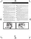
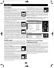
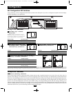
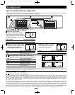
Feature Identification
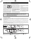
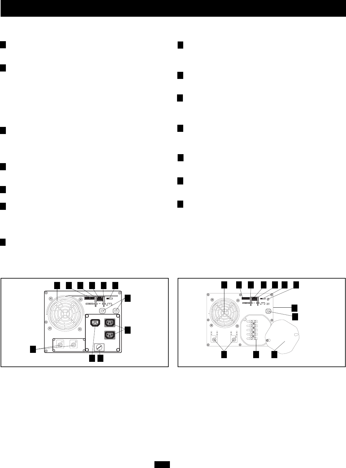
Identify the premium features on your specific model and quickly locate instructions on how to maximize their use.
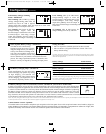
Configuration DIP Switches: optimize Inverter/Charger
operation depending on your application. See Configuration
Section for setting instructions.
Operating Mode Switch: controls Inverter/Charger operation.
The “AUTO/REMOTE” setting ensures your equipment
receives constant, uninterrupted AC power. It also enables the
Inverter/Charger to be remotely monitored and controlled with
an optional remote module (Tripp Lite model APSRM4, sold
separately). The “CHARGE ONLY” setting allows your batter-
ies to return to full charge faster by turning the inverter off
which halts battery discharging. See Operation Section for set-
ting instructions.
Operation Indicator Lights: intuitive “traffic light” signals
show whether the Inverter/Charger is operating from AC line
power or DC battery power. It also warns you if the connected
equipment load is too high. See Operation Section for instruc-
tions on reading indicator lights.
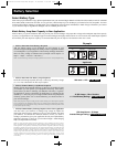
Battery Indicator Lights: intuitive “traffic light” signals show
approximate charge level of your battery. See Operation Section
for instructions on reading indicator lights.
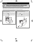
DC Power Terminals: connect to your battery terminals. See
Battery Connection Section for connection instructions.
AC Output Receptacles (not on hardwire models): IEC-320
output receptacle(s) allow you to connect equipment that you
would normally plug into a utility outlet. Select models also
include a Universal AC Output Adapter which allows you to
connect equipment with a wide variety of plug styles.
AC Input Receptacle (not on hardwire models): IEC-320
input receptacle connects the Inverter/Charger to any source of
utility or generator-supplied AC power when used with a user-
supplied cable with country-specific plug.
Hardwire AC Input/Output Terminal Strip (not on corded
models): securely connects the Inverter/Charger to facility or
vehicle electrical system. See Input/Output Connection Section
for connection instructions.
Resettable Circuit Breaker: protects your Inverter/Charger
against damage due to overload. See Operation Section for
resetting instructions.
Remote Control Module Connector: allows remote monitoring
and control with an optional module (Tripp Lite model
APSRM4, sold separately). See remote module owner’s manu-
al for connection instructions.
Battery Charge Conserver (Load Sense) Control (available
on select models): conserves battery power by setting the
low-load level at which the Inverter/Charger’s inverter automati-
cally shuts off. See Configuration Section for setting instructions.
Main Ground Lug: properly grounds the Inverter/Charger to
earth ground or to vehicle or boat grounding system. See Battery
Connection Section for connection instructions.
Thermostatically-Controlled Cooling Fan: quiet, efficient fan
regulates internal temperature and prolongs equipment service
life. Fan runs intermittently depending on temperature and load.
Hardwire AC Input/Output Cover Plate
Dead Battery Startup Feature (for all models, internal, not
shown): internal circuitry allows you to start up the
Inverter/Charger even with a dead battery connected to the unit.
As long as the Inverter/Charger is connected to a live utility- or
generator-supplied AC power source, the Inverter/Charger will
pass through AC power to connected equipment and charge con-
nected batteries.
1
2
3
4
5
6
7
8
9
10
11
12
13
14
OUTPUT/NEUTRAL
OUTPUT/HOT
GROUND
INPUT/NEUTRAL
INPUT/HOT
“FOR USE WITH COPPER WIRE ONLY”
1
24 3
5
9
10 1113
8 14
Front View (2012, 2424 & 3636 Hardwire Models).
12
Rear Mounted, Not Shown
Front View (750 & 1250 Corded Model)
1 24 3
5
6
9
1013
7
12
200711152 93-2752 230V APS OM.qxd 11/29/2007 2:15 PM Page 3