


6A
Configuration
(continued)
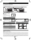
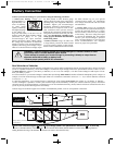
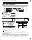
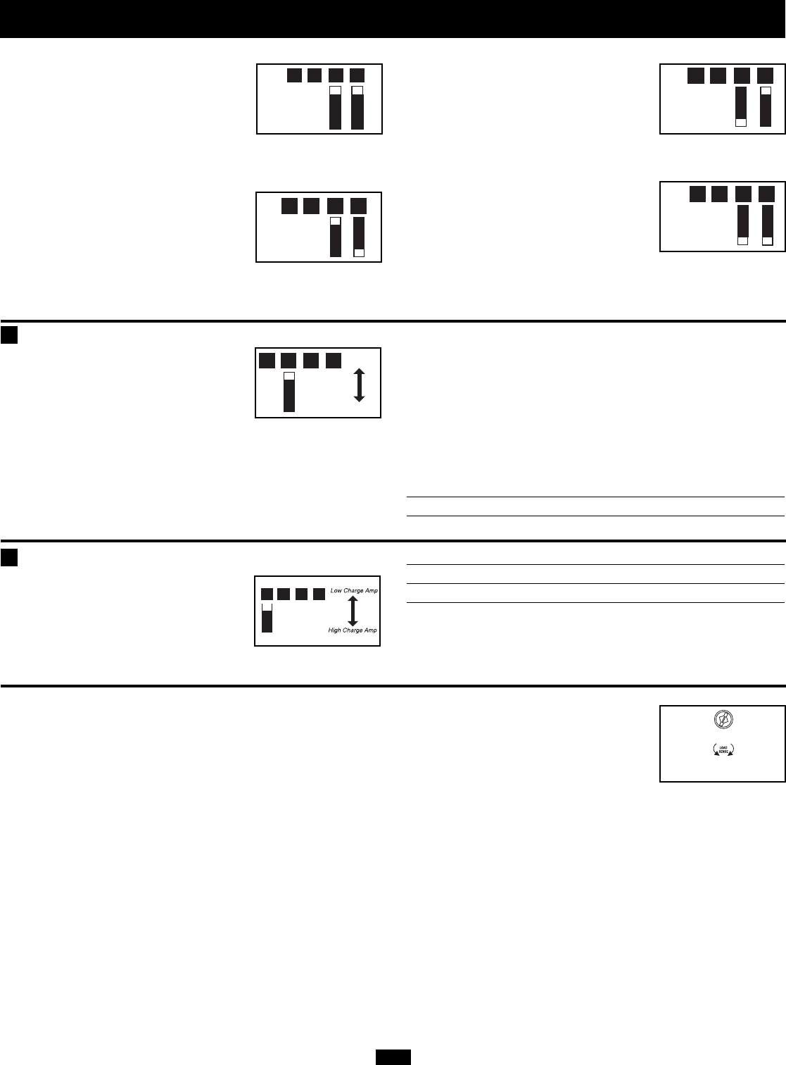
Set Battery Charging Amps—OPTIONAL
Check specifications for your unit’s high-
and low-charging amp options. By setting
on high charging, your batteries will
charge at maximum speed. When setting
on low charging, you lengthen the life of
your batteries (especially smaller ones).
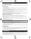
Battery Charger Switch Position
Low Charge Amps Up (factory setting)
High Charge Amps Down
CAUTION: When switching to the High Charge Amp setting, the user must ensure that the amp
hour capacity of their battery system exceeds the amperage of the High Charge Amp setting or
the batteries may be damaged or degraded.
Select Equalize Battery Charge—OPTIONAL
This DIP Switch is momentarily
engaged to begin the process of equal-
izing the charge state of your battery’s
cells by time-limited overcharge of all
cells. This can extend the useful life of
certain types of batteries; consult with your battery’s manufac-
turer to determine if your batteries could benefit from this
process. The charge equalization process is automatic; once
started, it can only be stopped by removing the input power.
Setting Procedure
• Move to “Equalize” (DOWN) position for three seconds.
• Move to “Reset” (UP) position and leave it there. This is the
factory default setting.
CAUTION: Do not leave DIP switch #3 in the down position after beginning process. Battery
charge equalization should only be performed in strict accordance with the battery manufacturer’s
instructions and specifications.
Battery Charge Switch Position
Reset Up (factory setting)
Equalize Down—momentarily
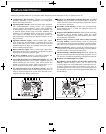
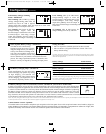
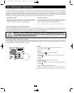
Select Battery Charger-Limiting
Points—OPTIONAL
Most Limiting (#B1 & #B2 Up, factory
setting): Charger-limiting takes effect the
moment any 230V AC load is applied;
charger output falls gradually from full output at no 230V load
passing through to no output at full load.
Less Limiting (#B1 Down & #B2 Up):
Charger-limiting begins when the
Inverter/Charger’s load reaches 33% of the
Inverter/Charger’s load rating. Charger
output falls gradually from full output at
33% of the Inverter/Charger’s load rating to about 33% of full output
at full load.
Least Limiting (#B1 Up & #B2 Down):
Charger-limiting begins at when the
Inverter/Charger’s load reaches 66% of the
Inverter/Charger’s load rating. Charger
output falls gradually from full output at
66% of the Inverter/Charger’s load rating to about 66% of full output
at full load.
No Limiting (#B1 & #B2 Down): No
charger-limiting occurs at any load size.
B1B2B3B4
B1B2B3B4
B1B2B3B4
B1B2B3B4
B1B2B3B4
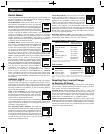
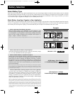
Set Battery Charge Conserver (Load Sense) Control—OPTIONAL (Not on 750 or 1250 models)
In order to save battery power, the unit's inverter automatically shuts off in the absence of any power demand from
connected equipment or appliances (the electrical load). When the Inverter/Charger detects a load, it automatical-
ly turns its inverter function on. Users may choose the minimum load the Inverter/Charger will detect by adjusting
the Battery Charge Conserver Control (see diagram). Using a small tool, turn the control clockwise to lower the
minimum load that will be detected, causing the inverter to turn on for smaller loads. When the control is turned
fully clockwise, the inverter will operate even when there is no load. Turn the control counterclockwise to increase the minimum load that
will be detected, causing the inverter to stay off until the new minimum load is reached.
NOTE: The factory setting for the control is fully clockwise. However, based on the threshold load to which you’d like the inverter to respond, you should adjust the control counterclockwise to reduce
its sensitivity until the inverter is active only when connected equipment or appliances are actually in use.
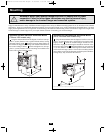
Connect Remote Control—Optional
All models feature an 8-conductor telephone style receptacle on the front panel for use with an optional remote control module (Tripp Lite
model APSRM4, sold separately). The remote module allows the Inverter/Charger to be mounted in a compartment or cabinet out of sight, while
operated conveniently from a remote location. See instructions packed with the remote control module.
"Reset"
"Equalize
"
B1B2B3B4
OFF
(LESSER
LOAD
ON)
MAX
(GREATER
LOAD
ON)
B4
B3
200711152 93-2752 230V APS OM.qxd 11/29/2007 2:15 PM Page 6