


2-4 Installation
DO NOT install forward incline, backward incline, in-line, or ventilator fans because these types of air
handlers are inadequate and inappropriate for this type of installation. If your contractor has any
questions concerning blower specifications or exhaust system requirements, please contact our Service
Department directly before installation.
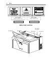
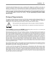
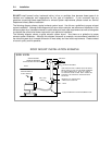
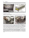
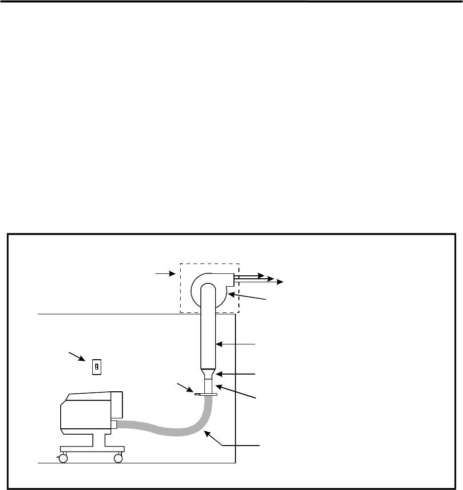
The following diagram shows a typical exhaust system layout. Use this as a guideline to proper exhaust
system installation. Although these diagrams just serve as an example, we recommend installation of the
exhaust system by a licensed contractor to meet safety and local code requirements as well as being able
to calculate the correct size blower required for your particular installation.
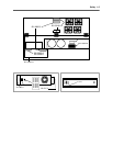
The following diagram shows a typical exhaust system layout. Use these as a guideline to proper
exhaust system installation. Although this diagram serves as an example, we recommend installation of
the exhaust system by a licensed contractor to meet safety and local code requirements. Please contact
a local air quality control specialist.
EXHAUST BLOWER
ROOF
EXHAUST
USE SMOOTH WALL TUBING SUCH AS SHEET
METAL OR PVC THAT IS THE SAME DIAMETER
AS THE BLOWER INLET. SEAL ALL JOINTS
TO PREVENT FUME LEAKS. KEEP TUBING AS
STRAIGHT AS POSSIBLE. BENDS REDUCE
AIR FLOW.
REDUCE TO 4 INCHES WITH
A REDUCING COUPLER
Y-PIPE
4 INCH DIAMETER FLEXIBLE RUBBER HOSE
SHUT OFF
GATE(S)
ROOF MOUNT INSTALLATION EXAMPLE
SIDE VIEW
WIRE BLOWER TO
A WALL SWITCH
SHIELD BLOWER
FROM THE WEATHER
WITH PROTECTIVE ENCLOSURE