


18
Super Finish 23 PLUS
1
2
3
4
5
6
GB
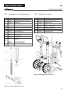
REPAIRS AT THE UNIT
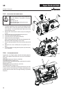
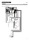
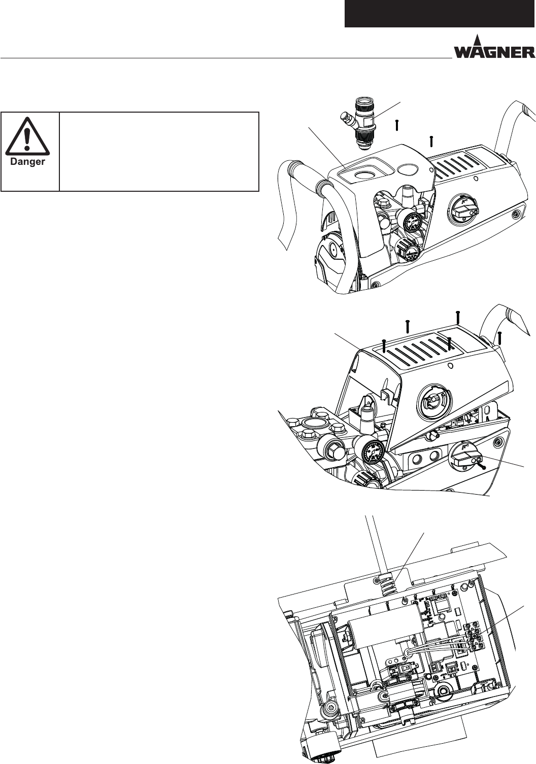
10.5 REPLACING THE POWER CABLE
This may only be carried out by a skilled elec-
trician. No liability is assumed for incorrect
installation.
Switch the unit o.
Before all repair work: Unplug the power
plug from the outlet.
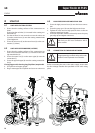
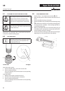
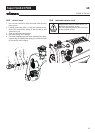
1. In models with a front cover unscrew the trigger housing
with inlet valve (1) from the paint section (see inlet valve,
10.2, sections 1 to 3) and remove the front cover (2) by
unscrewing the screws.
2. Remove the multi-function switch (3) by unscrewing the
screws.
3. Remove the rear cover (4) by loosening the screws.
4. Loosen the cable threaded joint (5).
5. Loosen the wires in the mains terminal (6).
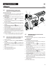
6. Replace the unit connecting line.
(only an approved power cable with the designation H07-
RNF with a splash-proof plug may be used).
7. Connect the green/yellow wire to the contact with the PE
sign.
8. Remount the covers carefully (do not squeeze any ca-
bles!)
9. Screw the trigger housing back into place (see inlet valve,
10.2, sections 3)
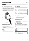
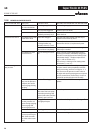
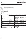
10.6 TYPICAL WEAR PARTS
Despite the use of high-quality materials the highly abrasive
eect of the paints means that wear can occur at the follow-
ing parts:
Inlet valve (spare part Order No.: 0344700)
For replacing refer to Section 10.2
(failure becomes noticeable through performance loss and/or
poor or no suction)
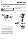
Outlet valve (spare part Order No.: 0341702)
For replacing refer to Section 10.3
(failure becomes noticeable through performance loss and/
or poor suction) The outlet valve is usually considerably more
durable than the inlet valve. Thorough cleaning may already
help here.