


16 ProSpray 3.25
GB
Servicing Repairs at the unit
10. Servicing
10.1 General servicing
Servicing of the unit should be carried out once annually by the
WAGNER service.
1. Check high-pressure hoses, device connecting line and plug
for damage.
2. Check the inlet valve, outlet valve and lter for wear.
10.2 High-pressure hose
Inspect the high-pressure hose visually for any notches or bulges, in
particular at the transition in the ttings. It must be possible to turn
the union nuts freely.
i
The risk of damage rises with the age of the high-
pressure hose. Wagner recommends replacing high-
pressure hoses after 6 years.
11. Repairs at the unit
Switch the unit OFF.
Before all repair work: Unplug the power plug from
the outlet.
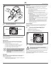
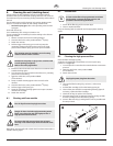
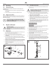
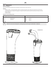
11.1 Relief valve
1. Useadriftpunchof2mmtoremovethegroovedpin(Fig.12,
Item 1) from the relief valve handle (2).
2. Remove the relief valve handle (2) and cam base (3).
3. Usingawrench,removethevalvehousing(4)fromthepump
manifold (6).
4. Ensure that the seal (5) is seated correctly, then screw the
new valve housing (4) completely into the pump manifold (6).
Tighten securely with a wrench.
5. Align the cam base (3) with the hole in the pump manifold (6).
Lubricate the cam base with grease and slide on the cam base.
6. Bring the hole in the valve shaft (7) and in the relief valve
handle (2) into alignment.
7. Insert the grooved pin (1) to secure the relief valve handle in
position.
3
7
4
1
2
6
5
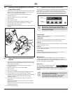
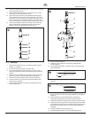
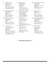
11.2 Inlet and outlet valve
1. Remove the four screws in the front cover and then remove
the front cover.
Danger of crushing - do not reach with the ngers or
tool between the moving parts.
2. Thepistonrodwillneedtobeinthelowerstrokeposition:
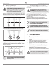
a. Turn the pressure control knob to minimum pressure. The
DESCscreenshouldsay“PRIME”.
b. Pressthe#1keyontheDESCcontrolpanel.The“CREEP
MODE”screenwillnowappear.
c. Slowly turn the pressure control knob clockwise to increase
the pressure. The crankshaft/slider assembly will begin to
move very slowly.
d. When it reaches the bottom, dead-center of its stroke, turn
the pressure control knob back to minimum pressure. The
crankshaft/slider assembly should stop.
3. Unplugthepowerplugfromtheoutlet.
4. Unit on high-rider cart:
Screw o the suction tube.
Unit on stand:
Remove the retaining clip from the connecting bend at the
suction hose and pull o the suction hose.
5. Screw o the return hose.
6. Swiveltheunit90°totherearinordertoworkmoreeasilyon
the material feed pump.
7. Remove the pusher stem clip and slide the pusher stem
housing (7) from the inlet valve housing (1).
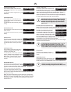
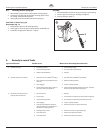
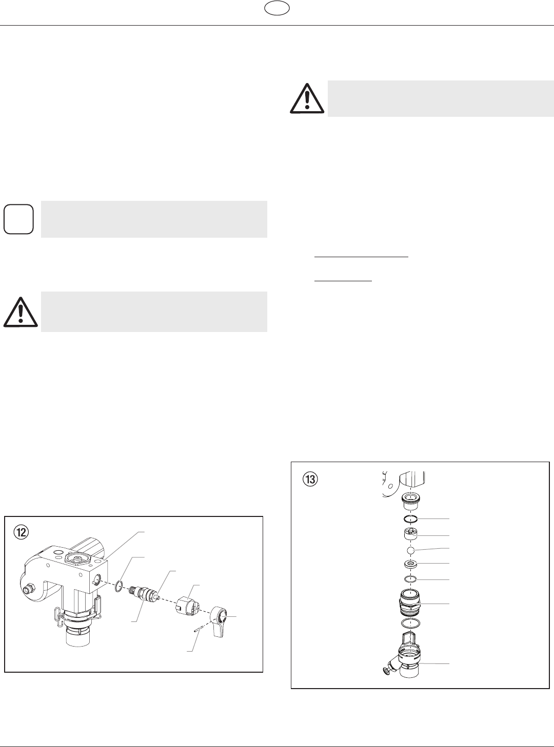
8. Unscrewtheinletvalvehousing(Fig.13,Item1)fromthe
pump manifold.
9. Remove the lower seal (2), lower ball guide (3), inlet valve ball
(4), inlet valve seat (5) and O-ring (6).
10. Clean all the parts with the corresponding cleaning agent.
Check the inlet valve housing (1), inlet valve seat (5) and inlet
valve ball (4) for wear and replace the parts if necessary. If the
worn inlet valve seat (5) is unused on one side, install it the
other way round.
4
5
6
1
2
3
7