


16
Finish 370 / 250
GB
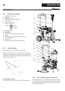
10 REPAIRS AT THE UNIT
Switch the unit o .
Before all repair work: Unplug the power
plug from the outlet.
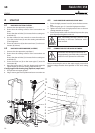
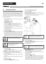
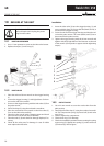
10.1 INLET VALVE PUSHER
1. Use a 17 mm spanner to screw out the inlet valve button.
2. Replace the wiper (1) and O-ring (2).
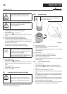
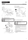
10.2 INLET VALVE
1. Place the enclosed 30 mm wrench on the trigger housing
(1).
2. Loosen the trigger housing (1) with light blows of a ham-
mer on the end of the wrench.
3. Screw out the trigger housing with the inlet valve (2) from
the paint section.
4. Pull of the clasp (3) using the enclosed screwdriver.
5. Place the enclosed 30 mm wrench on the inlet valve (2).
Turn out the inlet valve carefully.
6. Clean the valve seat (4) with a cleaning agent and brush
(ensure that no brush hairs are left behind).
7. Clean the seals (5, 6) and check for damage. Replace, if ne-
cessary.
8. Check all the valve parts for damage. In case of visible
wear replace the inlet valve.
REPAIRS AT THE UNIT
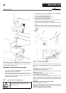
Installation
1. Insert the inlet valve (2) into the trigger housing (1) and
secure with the clasp (3). Ensure that the (black) seal (5) is
mounted in the trigger housing.
2. Screw the unit from the trigger housing and the inlet val-
ve into the paint section. The same (black) seal (7) has to
be mounted in the paint section.
3. Tighten the trigger housing with the 30 mm wrench and
tighten with three light blows of the hammer on the end
of the wrench. (Corresponds to approx. 90 Nm tightening
torque).
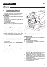
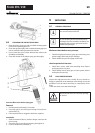
10.3 OUTLET VALVE
1. Use a 22 mm wrench to screw the outlet valve from the
paint section.
2. Carefully pull of the clasp (1) using the enclosed screwdri-
ver. The compression spring (2) presses ball (4) and valve
seat (5) out.
3. Clean or replace the components.
4. Check the O-ring (7) for damage.
5. Check the installation position when mounting the spring
support ring (3) (clipped onto spring (2)), outlet valve seat
(5) and seal (6), refer to gure.
1
2
2
5
3
1
6
4