


8
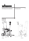
Finish 370 / 250
GB
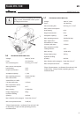
DESCRIPTION OF UNIT
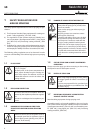
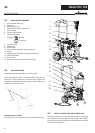
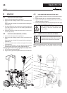
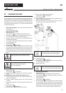
3.3 EXPLANATORY DIAGRAM
1 Tip guard with airless tip
2 Spray gun
3 High-pressure hose
4 Connection for high-pressure hose
5 Pressure gage
6 Pressure control valve
7 Pressure relef valve
Symbols: Spraying
Circulation
8 ON / OFF switch
9 Return tube
10 Suction tube
11 Connection for cleaning with the spray gun
12 Hopper
13 Cleaning ring (TopClean) for hopper (accessory)
14 Inlet valve button
15 Outlet valve
16 Oil measuring stick under the oil screw plug
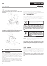
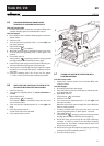
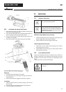
3.4 TRANSPORTATION
Unroll high-pressure hose and lay it over the shaft.
Pull the locking pins (Item 1) on both sides of shaft. The lo-
cking pins can be arrested by a small turn (left or right). Pull
the shaft out and deblock the locking pins. A light pull or push
will help to lock the pins well.
Transportation in vehicle
Secure the unit in the vehicle by means of suitable fasteners.
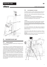
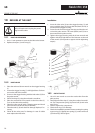
3.5 TROLLEY BACKFITTING ONLY FINISH 370
Pull locking pins (Item 1) on both sides of frame. The locking
pins can be arrested by a small turn (left or right). Move frame
into the other position. Deblock both locking pins so that they
t well in the rest position.
1 16
15
4
5
1
2
3
6
7
8
9
10
9
14
12
13