


GA 250AL_GA 400AL.
15
"
!
#
$
%
&
$
"?
(
"
$
'
#
)
&
"?
OPERATING MANUAL
EDITION 07 /2005 PART NO. DOC0350941
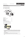
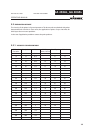
Fluid pressure
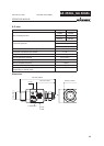
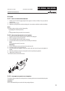
4.4 FUNCTION OF SPRAYGUN
4.4.1 DESIGN OF SPRAYGUN
Tension cap A
Control air connection B
Housing C
Paint connection D
Nozzle nut E
Flat jet nozzle F
Valve stem, see chapter 4.4.2 G
Compression spring, see chapter 4.4.2 H
•
The automatic gun GA 250AL or GA 400AL is controlled by way of the control air (B).
•
The control piston on the valve stem in the housing (C) of the spray gun GA 250AL or
GA 400AL has pressure applied to it and thereby opens the paint duct to the fl at jet
nozzle (F).
•
Closure takes place with the compression spring (H) after the pressure drop of the
control air (B) valve.
•
The set of seals (I) prevents that material can fl ow into the housing (C).
•
Secure the gun: Remove the air hose from the control air connection (B) on the spray
gun.
4.4.2 FUNCTIONAL DESCRIPTION