


Specifications
2 WATLOW DIN-A-MITE Style D User’s Manual
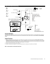
Operator Interface
• Command signal input and indication light
• Alarm output and indication light
Amperage
• Single-phase, 80A output maximum at 50°C (122°F) into a resistive
load. See the Output Rating Curve chart on page 3.
• Maximum surge current for 16.6 milliseconds, 1,800-amp peak
• Maximum I
2
t for fusing: 16,200 A
2
sec
• Latching current: 500mA minimum
• Holding current: 200mA minimum
• Off-state leakage: 1mA at 25°C (77°F) maximum
• 200KA SCCR type 1 and 2 approved with the recommended fusing
(see page 3)
Line Voltage
• 24 to 48VÅ (ac) units: 20 minimum to 53VÅ (ac) maximum
• 120 to 240VÅ (ac) units: 48 minimum to 265VÅ (ac) maximum
• 277 to 480VÅ (ac) units: 85 minimum to 528VÅ (ac) maximum
• 277 to 600VÅ (ac) units: 85 minimum to 660VÅ (ac) maximum
• 50/60 Hz independent +/- 5%
Control Mode, Zero Cross
• Input Control Signal Type C: VÎ (dc) input contactor. To increase
service life, the cycle time should be less than three seconds.
• Input Control Signal Type K: VÅ (ac) input contactor. To increase
service life, the cycle time should be less than three seconds.
• Input Control Signal Type F: 4 to 20mAÎ (dc) variable time base
control
Input Command Signal
• AC contactor
24VÅ ±10%, 120VÅ +10% / -25%, 240VÅ (ac) +10% / -25% @ 25mA
maximum per controlled leg
• Do not use the DIN-A-MITE Vac-input models with a temperature
controller that includes an RC snubber circuit across its output.
Remove the RC snubber circuit before placing the DIN-A-MITE into
service.
• DC Contactor
4.5VÎ to 32VÎ (dc): maximum current @ 4.5VÎ (dc) is 6mA per leg.
Add 3mA if alarm option is included
• Loop powered linear current
4mAÎ to 20mAÎ (dc): loop-powered. Input Type F0 and F1 options
only. (Requires current source with 6.2VÎ (dc) available. No more
than three DIN-A-MITE inputs connected in series)
Linearity (Input Control Signal Type F)
• Full on point 19.5 to 19.9mAÎ (dc), maximum voltage of 6.2V peak.
• ±5% input to output power accuracy, 0% to 100% of span (4.3 to
19.7mA or 12.3 to 19.7mA).
• Temperature stability is less than 0.15%/°C change.
Alarm
Shorted SCR Alarm Option
• Alarm state when the input command signal off and a 15A or more
load current is detected by the current transformer.
Alarm Output
• Energizes on alarm, non-latching
• Triac 24 to 240VÅ (ac) external supply with a current rating of 300mA
@ 25°C (77°F), 200mA @ 50°C (122°F), 100mA @ 80°C (176°F) and
a holding current of 200 µA with a latching current of 5mA typical
Current Sensing
• On-board current transformer (CT), typically 0.2VÅ (ac) output signal
per ampere sensed
Agency Approvals
• CE with proper filter:
89/336/EEC Electromagnetic Compatibility Directive
EN 61326: Industrial Immunity Class A emissions
Not suitable for Class B emissions environment
73/23/EEC Low Voltage Directive
EN 50178 Safety Requirements
• UL® 508-listed and C-UL
®
File E73741
Input Terminals
• Compression: Will accept 0.13 to 3.3 mm
2
(26 to 12 AWG) wire
• Torque to 0.5 Nm (4.4 in-lb) maximum with a 3.5 mm (1/8 in) blade
screwdriver
• Wire strip length 7 mm (0.28 in)
Line and Load Terminals
• Compression: Will accept 13.3 to 34 mm
2
(6 to 2 AWG) wire
• Torque to 9.0 to 10.1 Nm (80 to 90 in-lb) maximum with a 3/16 inch
Allen head
• Wire strip length 17.5 mm (0.69 in)
Operating Environment
• Operating temperature range: 0 to 85°C (32°F to 185°F)
• 0 to 90% RH (relative humidity), non-condensing
• Vibration: 2 g, 10 Hz to 150 Hz, applied in any one of three axes
• Storage temperature: -40 to 85°C (-40°F to 185°F)
• Insulation tested to 3,000 meters
• Installation Category III, pollution degree 2
Mounting
• Standard back panel mounting; fits the same mounting pattern as a
100 A, single-phase mercury displacement relay
• Mounting holes offer clearance for an M5 (No. 10) screw
• On-board semiconductor fusing, Bussmann part number 170N3437
Dimensions
• Height: 185 mm (7.28 in)
• Width: 66 mm (2.58 in)
• Depth: 239 mm (9.41 in)
• Weight: 2.9 kg (6.3 lb)
Specifications are subject to change without notice.