


WATLOW DIN-A-MITE Style D User’s Manual 5
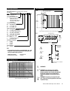
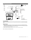
Single-Phase Output and Input Wiring
L1
2
1
Limit Control
Contacts
(if required)
L1 for all
voltages
Alarm or Current Transformer Output
Alarm or Current Transformer Output
(Model Number-Dependent)
Heater
4 to 20mA input:
(+)
(-)
4.5 to 32VÎ (dc) input:
(+)
(-)
Phase-to-neutral
100VÅ (ac) and above
The neutral must not be switched.
Phase-to-phase
200VÅ (ac)
and above
3
4
5
6
5
6
Current Sensing Option
DD10 - _ _ _ _ - 1 _ _ _
Current Monitor
or Indication
On-board
Current
Transformer
Semiconductor
Fuses
Non-latching Alarm Option
DD10- _ _ _ _ - S _ _ _
5
6
On-Board
Triac
VÅ
Alarm
Indicator
1A
Open Heater
Alarm Adjust
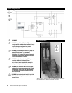
3
4
3
4
L2
Heater
Neutral
Ground lug supplied. Use
Thomas & Betts crimp tool
options below or equivalent.
Use 6 AWG copper conductor.
TBM 20S
TBM 25S
TBM 5
TBM 6
TBM 8
TBM 60RS
VÅ (ac) input
ç
Ó
2
Ó
3
Ó
4
Shorted SCR Alarm
The Watlow DIN-A-MITE alarm option provides an alarm output for shorted SCR conditions. A shorted SCR alarm is detected
when there is no command signal and a load current is detected. The alarm output is then energized. This is a non-latching
alarm.
Torque Procedure
1. While connecting the line and load wires, ensure that all wire strands are inside the connector. Do not allow loose wire
strands to hang out of the connector. Once you have installed the wire, torque these same connections to 9.0 to 10.1 Nm
(80 to 90 in-lb). Use a dial or digital-type torque wrench and hold the torque at 9.0 to 10.1 Nm (80 to 90 in-lb) for 30 seconds.
The 30-second hold allows the wire to settle, minimizing the wire cold flow.
2. Re-torque the same connections after 48 hours.
3. Develop a maintenance program to re-torque all load and line connections every three to six months.
NOTE: L1 and L2 terminals are 3/16-inch Allen head screws.