


11
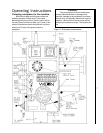
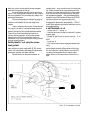
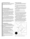
Spindle direction and power feed
The spindle can be driven clockwise or counter-
clockwise. The direction of rotation is controlled by
the control lever on the left hand side of the drill head.
See Fig. 1.
Clockwise or "forward" rotation is the direction
of rotation for right-hand tooling -- which is the vast
majority of tooling used in machine operations.
However, if you use left-hand tooling for any opera-
tions, the spindle direction can be set to counter-
clockwise or "reverse."
The power feed direction is determined by the
spindle direction. When the spindle is set to its most
common direction -- clockwise or forward -- the quill
and spindle are driven downward. When the spindle
direction is set to counterclockwise or reverse
direction, the quill and spindle are driven upward.
Hand feed -- roughing operations
When the feed levers are pushed toward the
drill head the power feed mechanism is disengaged.
In this position, the feed levers can be used to move
the quill and spindle and perform manual drilling or
other machining operations.
Fine hand feed using the power feed
system
The fine feed control wheel is located on the
underside of the right-hand side of the drill head.
See Fig. 1. The fine feed control is used as follows:
1. Set the feed rate dial to N -- neutral.
2. Pull the feed levers out so the power feed clutch is
engaged.
3. Turn the drill press POWER switch ON and set the
control lever so the spindle is turning in the correct
direction for the operation you are performing.
4. Turn the fine feed control wheel by hand. The
quill and spindle will move downward or upward
(depending upon which way you turn the wheel and
the direction the spindle is turning) until you stop
turning the control wheel.
the tooling is installed, you can restablish power to
the machine by turning the cut-out panel back ON.
This will reestablish power to the machine control
system and will allow you to use the motor which
raises and lowers the arm to position the tooling over
the work piece. Raising and lowering of the arm is
controlled by the control stick -- see Fig. 3 and read
page 7,
Raising and lowering the radial arm
.
Power ON light
When the cutout box power is ON, the POWER
light on the upper left hand side of the drill head (Fig.
1) will be lit. In this mode, power to the coolant pump
and to the spindle drive motor is controlled by the
switches on the control console.
Flood coolant control
The flood coolant system provided with the drill
press is turned on by turning the switch to the ON
position. Power OFF to the coolant pump is achieved
by turning the switch counterclockwise to its OFF
position. (If coolant does not flow, check the pump
rotation by observing the pump shaft. It should be
rotating in the direction of the arrow on the pump
casting. If it is not rotating in the correct direction,
see
Electrical,
for more information.)
Spindle motor controls
The power to the spindle motor controlled as
follows:
1. The cutout box control lever must be in the ON
position so power is being fed to the drill press.
2. The two speed spindle drive motor switch must be
in either HI or LOW position.
3. The control ON/OFF switch must be pushed ON.
4. The arm/spindle control lever must be pulled
forward (clockwise rotation) or backward (counter-
clockwise rotation.) See
Using the control lever,
page 11.
Turning spindle drive motor power OFF
To turn power OFF on the spindle drive motor do
one of the following:
1. Put the two speed motor switch in OFF position,
OR...
2. Push the Control ON/OFF switch off, OR...
3. Put the arm/spindle control lever in its middle
(neutral) position, OR...
4. Push the large, red emergency off STOP switch,
OR...
5. When servicing the tooling or other machine
components, put the service disconnect lever in OFF
position.
Once the STOP switch has been pushed (4.,
above) none of the other switches on the panel can
be used to control power to the spindle drive motor or
coolant pump until the STOP switch has been re-set.
Power ON and power OFF
If your Model 1230 was connected to its service
branch correctly, there will be a service disconnect
with an external power cutoff lever or switch which
disconnects the drill press from the service branch.
This is your ultimate protection against accidental
machine start-up when clamping work pieces to the
machine and/or inserting or removing tooling. Always
be certain you have turned off power at this discon-
nect before doing these operations.
Once your workpiece is clamped securely and