


9
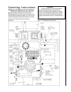
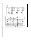
on LOW or HI speed. There is a chart on the front of
the drill head which shows you the spindle speeds
available and the gear change lever and motor switch
values required to select each speed. See Fig. 1.
On the gear change table you will also find the
recommended drill sizes for the various speeds which
are selectable. THESE RECOMMENDATIONS ARE
ONLY APPROXIMATE. With the wide variety of drill
types and coatings available, the variety of cutting
fluids which might be used, and the even wider
variety of work piece materials which you might be
machining -- you need to consult with your tooling,
coolant and/or work piece suppliers to determine the
best spindle speed to use for any specific drilling
operation.
CAUTION
NEVER swing the drill press arm using the
support column unless you are absolutely certain
the drill press base is firmly attached to the shop
floor. You can tell if the base is bolted to the floor
by checking the mounting pads at the four corners
of the base. There should be a securing bolt
through each mounting pad.
If the arm is moved off of its position directly
above the base and the base is not bolted to the
floor, THE DRILL MAY TIP OVER AND CAUSE
SERIOUS INJURY OR DEATH TO THE DRILL
PRESS OPERATOR (YOU!!) and will certainly
result in serious damage to the drill press, itself.
Don't take chances. Always look for bolts at the
mounting pads before swinging the drill press arm.
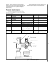
Setting spindle speed
Spindle speeds are established using the gear
change levers on the upper right-hand side of the drill
head. (See Fig. 1.) The shorter of the two levers
operates a two-speed mechanism which puts the
gearbox in either high gear or low gear. There is a
"HI/LOW" readout on the upper left hand side of the
drill head which tells you which speed range is
selected.
The longer gear change lever operates a three
speed gearbox mechanism. The lowest gear and
spindle speed is selected by pushing the lever away
from you -- that is, by rotating the change shaft
counterclockwise. The highest gear and spindle
speed is selected by pulling the lever toward you --
rotating the shaft clockwise. There is a detent in the
middle of the lever travel to tell you when the lever is
in the intermediate gear position.
This gearbox set-up gives you a total of six
spindle speeds which may be selected. The two-
speed spindle drive motor, therefore, increases the
number of available spindle speeds to 12. The
specific spindle speed selected clearly depends on
the position of
both gear change levers
and whether
the
motor switch
on the top front of the drill head is
Caution
Do not try to change gears while the spindle
is turning. This may cause serious damage to the
spindle drive system.
Allow the spindle to come to a complete stop
before attempting to change gears. If the gear
change lever you want to move does not slip
easily into the new position you require, jog the
motor for a second using the control lever. Then
allow the spindle to come to a stop again before
attempting to change gears, again. Repeat this
jogging process, as necessary, until the gears
match up properly for changing.
Setting feed rate and depth of cut
The Model 1230 has limit switches on the quill
which cuts off electric power to the drive motor when
the quill has reached either the upper or lower limit of
its travel. This system is designed to prevent gearbox
damage if the power feed mechanism is engaged --
damage which would occur if the quill were to bottom
out against the upper or lower limit of quill travel. In
the event of failure of either limit switch there is also a
safety clutch mechanism which will slip when the
limits of travel are reached.
However, while you are able to use virtually the
full travel of the quill for drilling or other operations,
the drill press operator typically sets both the rate of
feed -- travel-per-revolution of the spindle -- and the
depth of cut -- that is, the total distance the quill
moves to make the required depth of cut.
These two operations are described, here:
Setting feed rate
The feed rate is set using the knob and dial on
the front of the drill head. See Fig. 1. The knob on
the dial can be rotated to select any of three different
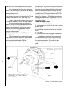
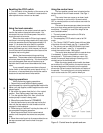
Moving the arm on the support column
1. Power to the drill press must be ON -- then
release the machine locks by pushing the UNLOCK
push button.
2. Use the handle at the end of the arm (see Fig. 1)
to move the column (and, therefore, to swing the arm)
as necessary to the required spindle position.
3. When the spindle is positioned correctly and no
other adjustments are quired, push the LOCK push
button to re-lock all machine locks.