


10
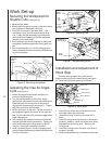
Work Set-up
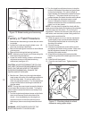
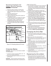
Securing the Workpiece for
Square Cuts
(see figure 5)
1. Raise the saw head.
2. Slide the left vise jaw far enough to the left to allow
the workpiece to be placed in the vise.
3. Place the workpiece on the work table. If the
workpiece is long, provide support at the other
end. It may also be necessary to provide addi-
tional downward clamping to hold the workpiece
securely on the work table.
4. Turn clamping hand wheel clockwise to clamp the
workpiece in position against the fixed (right) vise
jaw.
5. After completing the cut, turn the clamping hand
wheel counterclockwise and slide the left jaw away
from the workpiece.
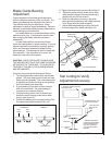
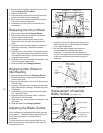
Adjusting the Vise for Angle
Cuts
(see figure 6)
1. Loosen the angle locking screw and the pivot
screw on the left vise jaw.
2. Turn the locking handle on the round, angle-
setting block counterclockwise to unlock the block.
Slide the block until the pointer on the block is
aligned with desired angle (see figure 7). Tighten
the locking handle to set the angle.
3. Set the workpiece in the vise. Put the front end of
the workpiece against the corner of the right vise
jaw. Put the rear end of the workpiece against the
angle-setting block.
4. Turn clamping hand wheel clockwise until the left
vise jaw is parallel with the workpiece. Tighten the
pivot screw and angle locking screw on the left
vise jaw. Clamp the workpiece in position.
5. After completing the cut, turn the clamping hand
wheel counterclockwise and slide the left jaw away
from the workpiece.
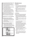
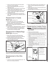
Installation and Adjustment of
Work Stop
The work stop is used to set up the saw for
making multiple cuts of the same length (see figure
8). Install and adjust the work stop as follows:
1. Insert the end of the stop rod in the hole in the
front right side of the work table.
2. Tighten the “wing” screw to secure the rod in
place.
3. Install the stop post in the channel on the back of
the stop L-bracket. Install the locking lever in the
threaded hole in the stop post. Snug-up the
locking lever.
4. Install the locking knob in the hole in the side of
the stop L-bracket.
5. Slide the assembled stop L-bracket onto the stop
Figure 5: Securing workpiece
Clamping
Hand
Wheel
Work Table
Left Vise Jaw
Saw Head
Figure 6: Adjusting vise
Figure 7: Angle setting block
Set Workpiece
Against Corner
of Right
Vise Jaw
Angle
Setting
Block
Pivot
Screw
Angle
Locking
Screw
Left
Vise
Jaw
Angle Block
Locking Handle
Angle
Pointer
Figure 8: Work stop
Stop Rod
Knob
Stop Post
Locking Lever
"Wing" Screw
Stop L-Bracket