


12
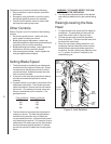
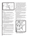
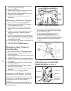
Figure 10: Blade tracking and tensioning
Blade Tracking
Hex Adjustment
Screws
Center
Locking
Screws
Single
Adjustment
Screw
screws.)
Factory or Field Procedure
1. Raise the saw head enough to allow the saw motor
to operate.
2. Loosen four knobs securing the blade cover. Lift
the cover and swing it backward.
3. Remove the blade guard mounted on the left blade
guide support.
4. Remove both blade guide bearing brackets.
NOTE: Maintain proper tension at all times using the
blade tensioning mechanism.
5. Loosen the center locking screws in all three hex
adjustment screws on the blade tensioning
mechanism (see figure 10).
CAUTION: WHILE PERFORMING THE FOLLOW-
ING, KEEP THE BLADE FROM RUBBING EXCES-
SIVELY ON THE SHOULDER OF THE WHEEL.
EXCESSIVE RUBBING WILL DAMAGE THE
WHEEL AND/OR THE BLADE.
6. Start the saw. Slowly turn the single hex adjust-
ment screw at the rear of the tracking mechanism
to tilt the idler wheel. Do not turn either of the
other two adjustment screws. Turn the adjustment
screw until the blade is touching the shoulder of
the idler wheel.
NOTE: Turning the screw inward causes the blade to
move toward the shoulder of the wheel. Turning the
screw outward causes the blade to move away from
the shoulder.
7. Turn the single hex adjustment screw so the blade
starts to move away from the shoulder of the
wheel — then immediately turn the single hex
adjustment screw in the other direction so the
blade stops, then moves slowly toward the shoul-
der.
WARNING: KEEP FINGERS CLEAR OF THE
BLADE AND WHEEL TO AVOID INJURY.
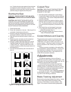
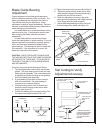
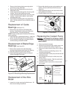
8. Turn the single hex adjustment screw to stop the
motion of the blade on the wheel as it gets closer
to the wheel shoulder. Put a 6-inch length of
paper between the blade and the wheel as shown
in figure 11. The paper should not be cut as it
passes between the wheel shoulder and the blade.
9. Turn the single hex adjustment screw a small
amount. Repeat the insertion of the paper
between the wheel shoulder and the blade until the
paper is cut in two pieces.
NOTE: You may have to repeat the check with the
paper several times before the blade and the shoulder
cuts the paper into two pieces. Do not hurry the
adjustment. Patience and accuracy here will pay off
with better, more accurate, quieter cutting and much
longer machine and blade life.
10. When the paper is cut, turn the hex adjustment
screw slightly in the counterclockwise direction.
This assures that the blade is not touching the
shoulder of the wheel.
11. Shut off the saw.
12. Hold the hex adjustment screws with a wrench
and tighten the center locking screws. Make sure
the hex adjustment screws do not move while
tightening the center screws.
13. Install the two blade guide bearing brackets.
Position the guides so the bearings just touch the
blade.
14. Install the left blade guard.
15. Close the saw head cover. Tighten the four
knobs.
Figure 11: Checking blade-to-wheel
clearance using paper strips
Motor "ON"
Upper Wheel
Rotating
Put Strip
Between
Wheel
and
Blade