


13
Blade Guide Bearing
Adjustment
Proper adjustment of the blade guide bearings is
critical to efficient operation of the cut-off saw. The
blade guide bearings are adjusted at the Factory.
They should rarely require adjustment. When
adjustment is required, adjust immediately. Failure to
maintain proper blade adjustment may cause serious
blade damage or inaccurate cuts.
It is always better to try a new blade when cutting
performance is poor. If performance remains poor
after changing the blade, make the necessary
adjustments.
If a new blade does not correct the problem,
check the blade guides for proper spacing. For most
efficient operation and maximum accuracy, provide
0.001 inch clearance between the blade and the
guide bearings. The bearings will still turn freely with
this clearance. If the clearance is incorrect, the
blade may track off the drive wheel.
CAUTION: CHECK THE BLADE TO MAKE SURE
THE WELDED SECTION IS THE SAME THICKNESS
AS THE REST OF THE BLADE. IF THE BLADE IS
THICKER AT THE WELD, THE GUIDE BEARINGS
MAY BE DAMAGED.
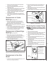
If required, adjust the guide bearings as follows:
1. Two blade guides are used in each set of blade
guides. The inner blade guide is fixed; the outer
blade guide is adjustable. The outer blade guide
is adjusted using a knurled knob on the operator
side of the blade guide assembly.
2. A guide bearing is provided on the innermost
side of the saw blade. The guide bearing is
mounted on an eccentric bushing.
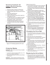
3. Hold the bushing with a 3/4-inch wrench and
loosen the center locking screw with an Allen
wrench (see figure 12).
4. Position the bearing by turning the bushing. Set
the clearance at approximately 0.001 inch.
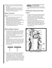
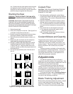
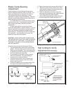
Figure 12: Blade-To-Blade Guide Orientation
5. Tighten the center locking screw with an Allen 5.
5. Tighten the center locking screw with an Allen
wrench while holding the eccentric bushing in
position with the 3/4-inch wrench.
6. When the adjustment is correct, the guide
bearing should rotate freely with slight pressure
of the finger (with the blade stopped).
7. Adjust blade-edge bearings so they just touch
the back edge of the blade (see figure 19).
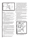
Figure 13: Adjustment of Guide Bearing
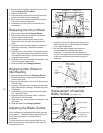
Figure 14: Cutting a Test
1. Clamp in vise and mark top
of barstock here
2. Cut off a slice of
the bar stock
3. Rotate stock in vise
so mark is at bottom
4. Cut off a new
slice from the
stock
5. Measure
here...
New slice
7. Differences between
measurements at edges
of disc should be less
than .003 inches per
inch per side of stock
diameter
6. ...measure
here
INCORRECT CORRECT
Outer
Roller
Inner
Roller
Locking Screw
Concentric Bushing
Socket Cap Screw
Blade Guide
Bearings
Carbide
Guides
Knurled Knob
Eccentric
Bushing
Test Cutting to Verify
Adjustment Accuracy