


16
1. Loosen the knob on the blade guide support and
slide the guide left or right as required. Repeat
for the other blade guide.
2. Set the blade guide supports as required to
accommodate the width/diameter of the
workpiece. The blade guides should be posi-
tioned so the guides do not contact the workpiece
as the saw head moves downward through the
workpiece.
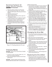
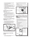
Replacement of Carbide
Blade Guides
(see figure 19)
2. Remove the drive belt from the drive motor pulley
(see Changing the Drive Belt).
3. Remove motor pulley.
4. Open the motor junction box and disconnect the
power cord wires from their terminals.
5. Remove the nuts, washers and bolts that secure
the motor to the mounting plate.
6. Installation of a new motor is a reversal of the
above steps.
Replacing the Drive Wheel
1. Remove the blade (see Changing Blades).
2. Remove the screw, spring washer, and washer
from the speed reducer shaft.
3. Pull the wheel from the speed reducer shaft.
Remove the drive key from the speed reducer
shaft.
4. Inspection: Examine drive edge and shoulder of
the wheel for damage. Replace the wheel if
damaged.
5. Install the key in the keyway in the speed reducer
shaft. Align the keyway in the wheel with the key
in the speed reducer shaft. Reinstall the wheel on
the speed reducer shaft.
6. Install the screw, spring washer and washer in the
end of the speed reducer shaft.
7. Install the blade (see Changing Blades).
Replacing Idler Wheel or
Idler Bearing
1. Remove the saw blade (see Changing Blades).
2. Remove the screw, spring washer, and washer
from the idler shaft.
3. Remove the idler wheel. Remove the bearing from
the idler wheel.
4. Inspection: Examine the drive edge and shoulder
of the idler wheel for damage. Replace the wheel
if damaged.
5. Inspect bearings for damage and smooth opera-
tion, Replace if faulty.
6. Install the bearing in the idler wheel. Install the
idler wheel on the idler shaft.
7. Install the screw, spring washer and washer in the
idler shaft.
8. Install the blade (see Changing blades).
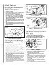
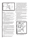
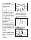
Adjusting the Blade Guides
The cut-off saw has adjustable blade guide supports
(see figure 17). The blade guide supports allow you
to set the blade guides for varying widths of
workpieces.
To make accurate cuts and prolong blade life, the
blade guide supports should be set to just clear the
workpiece to be cut.
Lock
Handle
Left
Guide
Support
Scale (Metric) Scale (Inches)
Lock
Handle
Right
Guide
Support
Figure 17: Blade Guide Supports
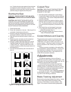
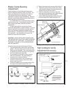
Blade Tracking
Hex Adjustment
Screws
Single
Adjustment
Screw
Center
Locking
Screws
Figure 18: Blade Guide Features
Figure 19: Carbide Blade Guide Replacement
Guide Support
Chip Brush
Eccentric-Mounted
Guide Bearing
Adjusting Knob
Blade Guides
Blade Edge
Bearing (2)
Coolant Line