


90-0115-00
10/97 Fltman.pm65
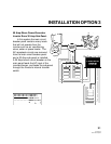
This procedure will connect the chassis
of your unit to AC ground. In addition, the
AC input and AC output green wires are
connected to chassis ground. It is important
to connect these wires to the AC ground bus
in the circuit breaker panel.
Note: The battery cables are not con-
nected to ground or the chassis of the unit.
Neutral Bonding
For safety purposes, the Fleet Power
inverter/charger unit internally bonds the AC
output neutral to the AC ground when the
unit is OFF or in the inverter mode. When
incoming AC power is applied and the
transfer switch is engaged, the internal
neutral-to- ground bond is automatically
lifted.
This means that when the vehicle is
connected to shore power, the grounding
system is connected to the shore power
ground, where neutral and earth ground are
bonded together. This technique insures
safety in all conditions and conforms to the
requirements of the NEC.
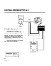
AC Wiring
The AC wires route through the holes in
the bottom of the unit. Use a screwdriver to
remove the screws which secure the AC
wiring compartment cover plate. Inside, the
compartment is divided into 2 sections, one
labeled AC Input, the other labeled AC
Output. Each side contains 3 pigtails:
black, white and green. Six wire nut con-
nectors are also provided.
Black Hot or Line
White Neutral
Green Ground
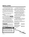
Conventional metal strain reliefs are
provided. These can be replaced by plastic
strain reliefs for additional corrosion resis-
tance or 3/4 inch conduit fittings if the wiring
will be routed through the conduit.
Use proper wire sizes according to the
NEC.
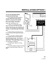
AC Input (Fleet Power 1000 and Fleet
Power 2000): Feed the 3 conductor AC
input wire through the strain relief and into
the AC input compartment. You should
have 6 inches of individually insulated
black, white and green wire. Strip 1/2 inch
of insulation off each conductor and connect
to the pigtails: black to black, white to white
and green to green.
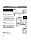
AC Input (Fleet Power 2500): There
are 2 options for configuring the AC input to
the Fleet Power 2500.
Dual Inputs: The internal battery
charger may be fed separately from the
transfer input which feeds the AC loads. In
this case, connect one 30 Amp feed to the
charger pigtails and another 30 Amp feed to
the transfer switch input.
Connecting the feeds in this way bal-
ances the AC loads when 2 legs of incoming
AC power are available. These two feeds
can be in or out of phase. Transfer will only
INSTALLATION
25