


90-0115-00
10/97 Fltman.pm65
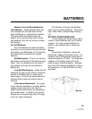
REMOTE CONTROL PANEL
Use the 5 Amp setting for small genera-
tors, or for charging deeply discharged
batteries.
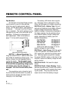
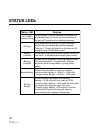
Dip Switch Status
You can check the position of the dip
switches by quickly cycling the power switch
OFF/ON twice. The DC Volts bargraph will
cease to display battery voltage and will
indicate the settings of each dip switch. In
this mode the bottom LED will illuminate if
switch 1 is on; the second LED will illumi-
nate if switch 2 is on, etc. Dip switch set-
tings are indicated for 10 seconds after
which time the display returns to indicating
battery voltage.
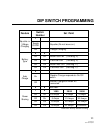
Factory default settings for all dip
switches are in the Off position.
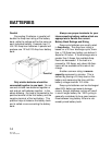
Remote Control Wiring
The remote control panel is supplied
with 25 or 50 ft. of telephone cable. The
cable supplied may be 6 conductor, how-
ever, only 4 conductor is required. You may
buy standard 4 conductor telephone cable
and run up to 50 ft., if desired. Use only a
single length of telephone wire, do not
splice.
Refer to page 11 for the Dip Switch
Programming chart.
9