


90-0115-00
10/97 Fltman.pm65
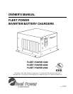
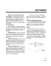
REMOTE CONTROL PANEL
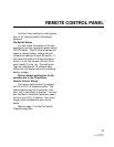
Dip Switches
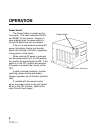
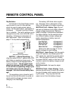
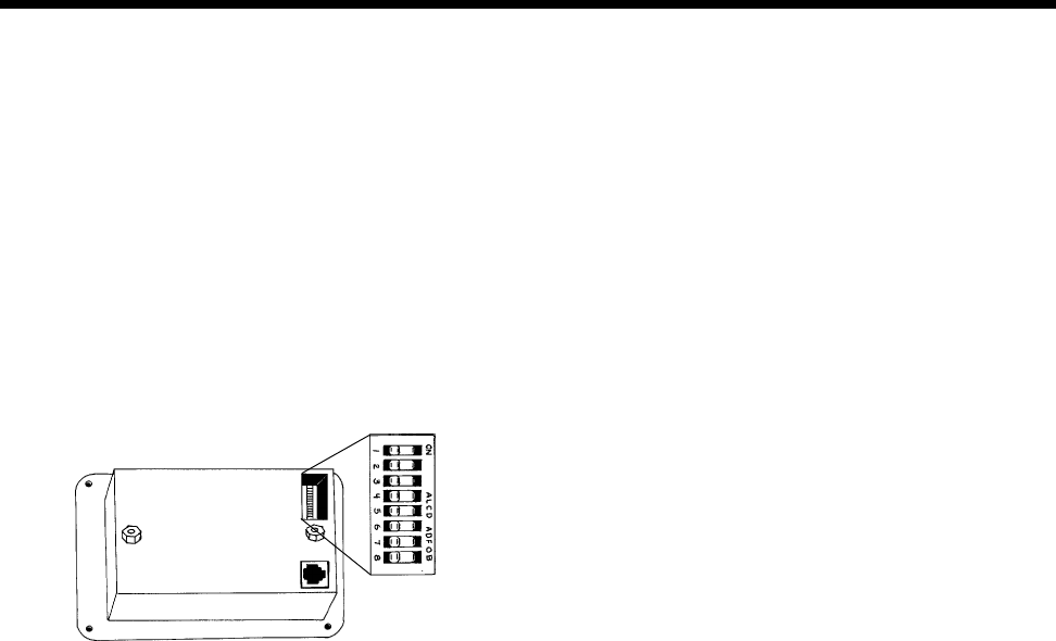
On the back of the Fleet Power remote
control panel is a set of 8 dip switches
which are used to make several adjust-
ments. On the switch block, each switch is
numbered . . .1 through 8 and the ON posi-
tion is indicated. The switch settings can be
changed at any time, even while the unit is
operating. Following is a discussion of
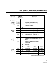
each adjustment. Refer to the table on
page 11 for dip switch programming.
SWITCH 1 -
Manual Equalizing
Cy-
cling this switch ON for 1 second, then OFF,
will initiate an equalizing charge cycle. The
battery charger must be engaged before
cycling the switch. The dip switch must
always be returned to the OFF position.
If it is left ON, an equalizing charge cycle
will initiate every time the charger is
engaged - this could cause battery dam-
age.
The equalizing cycle is timed to last 8
hours from the time the switch is cycled, at
which point the charger resumes normal
charging in the float stage.
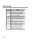
The battery LED blinks when equaliz-
ing. See page 18 for a discussion of the
theory and procedure for battery equalizing.
SWITCH #2 & #3 -
Battery Type
Gel cell
and wet cell batteries have slightly different
charge voltage requirements. Optimum
battery charging is temperature dependent.
For these reasons, the dip switches allow
four different battery charger voltage set
points, depending on battery type and
ambient temperature:
Cool Wet Cell < 80 degrees F.
Warm Wet Cell > 80 degrees F.
Cool Gel Cell < 80 degrees F.
Warm Gel Cell > 80 degrees F.
Refer to the table on page 21 for the
specific voltages for each setting.
SWITCH #4 -
Auto Charge
With the switch
in the OFF position, the remote panel ON/
OFF switch only controls the inverter opera-
tion. With the switch turned ON, it allows
the power ON/OFF switch on the front of the
remote to control the battery charger as well
as the inverter.
SWITCH #5 & #6 - Not used for adjust-
ments.
SWITCH #7 & #8 -
Power Sharing
These
switches should be set to match the value of
the circuit breaker which protects the incom-
ing AC power. They may also limit the
output current from the battery charger.
8
BACK VIEW
Fleet Power Remote Control Panel