


22
CAUTION Risk of electrical shock. Do not
remove cover, no user serviceable parts
inside. Refer servicing to qualified service
personnel.
The Freedom Combi is appropriate for
installation in recreational and commercial
maritime applications.
It is recommended that installation be
completed by an authorized Xantrex technical
dealer or experienced marine electrician.
Key Installation Points
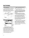
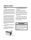
1. The unit is designed to mount vertically
(bulkhead) or horizontally (on a shelf).
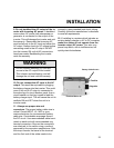
2. Allow several inches of clearance around
the unit to permit a supply of fresh air to the
cooling fan. Do not block any of the vents or
louvers. The thermostat controlled fan pulls air
from outside the unit. It pulls air across the
internal components, particularly the trans-
former and heat sinks, then out the fan vent.
3. Keep the inverter/charger out of the
elements and out of direct contact with
water or spray. Failure to do so may result in
premature malfunction from corrosion and void
the warranty.
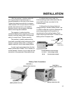
4. Mount the unit as close to the batteries
as possible but not in the presence of
flammable fumes or in an unvented battery
compartment. Keep the overall length of each
battery cable less than 10 feet.
Note: For more information on inverter
location selection refer American Boat and
Yacht Council (ABYC) recommendation A-25.
Refer to page 33.
INSTALLATION
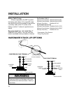
5. Do not connect the inverter battery
negative cable to the vessel safety
ground. Run the negative (-) cable directly to
the battery bank. If the positive (+) and negative
(-) cables run parallel to each other, twist the
cables together. This will minimize the
inductive adverse effects of cable length. Be
sure the cable size meets with NEC
requirements for your installation.
6. Make sure all wiring conforms to local
and national electrical codes. If in doubt,
consult ABYC, NEC, or a qualified marine
electrician.
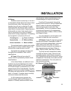
7. To meet electrical codes, a UL Listed DC
Rated slow blow fuse must be installed in the
positive battery cable within 7 inches of the
current source. Unless the conductor is
attached to the battery terminal, then it must be
within 72 inches (ABYC standard). This fuse is
intended to protect the battery and cables
against a short circuit. The inverter is protected
internally and will not blow a properly sized fuse.
8. Do not connect the battery until you
have read the remainder of the installation
section. Observe proper polarity when
connecting batteries. Reverse DC polarity will
result in damage to the unit and will void the
warranty. Use care when making the DC
connections.
The Freedom Series is not DC reverse
polarity protected. Be very careful to
connect the negative and positive cables
correctly, otherwise damage will result and
the warranty will be void.
WARNING