34
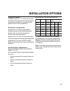
INSTALLATION OPTIONS
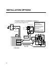
AC Output 2
AC Output 1
AC Input 2
AC Input 1
Ground Bus
Neutral Bus
Cap* Off each
wire separately
Inverter AC Sub Panel
To
Inverter
AC
Loads
12 VDC Battery Bank
Class T
Fuse
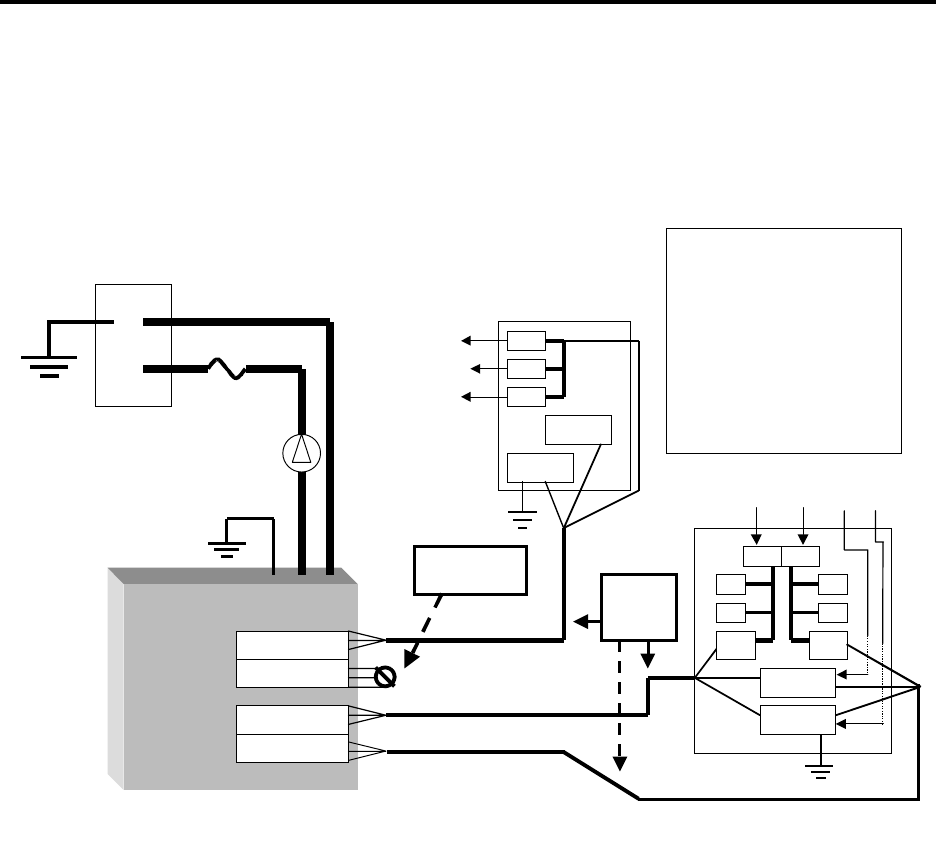
Freedom Marine Installation Option 3
Freedom Marine Model 25, 30
Dual Input/ Single Output
30 Amp Transfer
Separate Charge Input
Power Sharing Not Active
AC ground and DC ground are
shown connected, therefore,
galvanic protection is
recommended.
**Always consult Local and National
Electrical Codes for proper wire size
prior to installation
Freedom Marine
Inverter/Charger
10/3
AWG
Wire**
-
+
+
-
Hot
Bus
Neutral Bus
Ground Bus
30
From Shore or Generator
L2
Gnd
Main AC Panel
30
Battery Switch
AC Wire Colors
Hot = Black
Neutral = White
Ground = Green
L1 Neu
Main Main


