


975-0390-01-01 7
Features
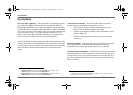
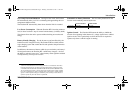
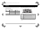
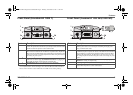
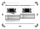
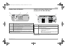
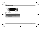
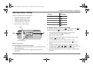
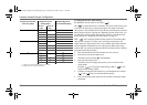
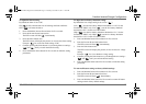
Display Panel (All Models) Remote and Power Module Panel
(
Freedom HF 1055 EMS,1800 EMS
)
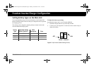
For instructions on how to enable or disable Ignition Control, see the
Installation Guide.
Feature Description
1 Inverter Power button is the main unit switch that turns the Freedom HF’s
inverter function ON or OFF. See page 14 for additional information.
2 Three-digit LED display screen shows status information and fault codes.
See page 14 for additional information.
3 Status LED indicates the mode of operation with a three-color LED. See
page 14 for additional information.
4 Select button changes status information displayed on the display screen. See
page 14 for additional information.
IMPORTANT: See “Display Panel Operation” on page 14 starting on page 14 for detailed
information on operating the panel’s buttons.
FREEDOM HF
InputVoltage(V)
Select
STATUS
Battery
Fault
Utility
Input Current (A)
Output Power (kW)
4
1
2
3
Feature Description
1 Remote jack is used for connecting the Display panel that ships with the
Freedom HF 1055 EMS and 1800 EMS. Each shipment comes with a 25-foot
communications cable as well.
2 Power module has one fuse and three contacts for wires that connect to:
• an auxiliary 12-volt DC OUT terminal,
• an Ignition Control terminal, and
• a Disabled terminal.
NOTE: The Ignition Control and Disabled terminals are connected by
a jumper wire that acts to disable ignition control. Removing the
jumper wire will enable ignition control.
2
1
Freedom HF InvChg Owners Guide.book Page 7 Thursday, November 24, 2011 11:20 AM