DM9161B
10/100 Mbps Fast Ethernet Physical Layer Single Chip Transceiver
29 Final
Version: DM9161B-12-DS-F01
January 31, 2008
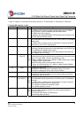
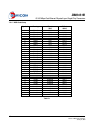
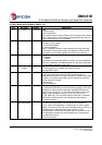
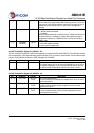
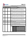
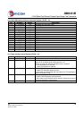
latched into this bit at power-up/reset
1 = Enable Reduced MII
0 = Normal MII
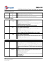
16.7 F_LINK_100 0, RW Force Good Link in 100Mbps
1 = Force 100Mbps good link status
0 = Normal 100Mbps operation
This bit is useful for diagnostic purposes
16.6 SPLED_CTL 0, RW Speed LED Disable
1 = Disable SPEED LED output and enable SD signal monitor (for
internal debug). When this bit is set, it controls the SPEED LED as
100BASE-X SD signal output .For debug only.
0 = Normal SPEED LED output to indicate speed status
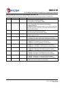
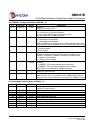
16.5 COLLED_CTL 0, RW Collision LED Enable
1 = FDX/COL LED output is configured to indicate
Full-duplex/Collision status
0 = FDX/COL LED output is configured to indicate Full/half duplex
status
16.4 RPDCTR-EN 1, RW Reduced Power Down Control Enable
This bit is used to enable automatic reduced power down
1 = Enable automatic reduced power down
0 = Disable automatic reduced power down
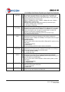
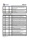
16.3 SMRST 0, RW
Reset State Machine
When writes 1 to this bit, all state machines of PHY will be reset.
This bit is self-clear after reset is completed
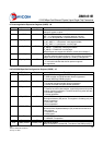
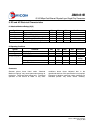
16.2 MFPSC 1, RW
MF Preamble Suppression Control
MII frame preamble suppression control bit
1 = MF preamble suppression bit on
0 = MF preamble suppression bit off
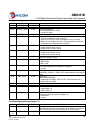
16.1 SLEEP 0, RW
Sleep Mode
Writing a 1 to this bit will cause PHY entering the Sleep mode and
power down all circuit except oscillator and clock generator circuit.
When waking up from Sleep mode (write this bit to 0), the
configuration will go back to the state before sleep; but the state
machine will be reset
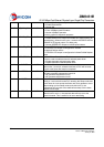
16.0 RLOUT 0, RW
Remote Loop out Control
When this bit is set to 1, the received data will loop out to the
transmit channel. This is useful for bit error rate testing