Triggering on Waveforms
TDS 684A, TDS 744A, & TDS 784A User Manual
3–53
Displaying pretrigger information can be valuable when troubleshooting. For
example, if you are trying to find the cause of an unwanted glitch in your test
circuit, it might trigger on the glitch and make the pretrigger period large enough
to capture data before the glitch. By analyzing what happened before the glitch,
you may uncover clues about its source.
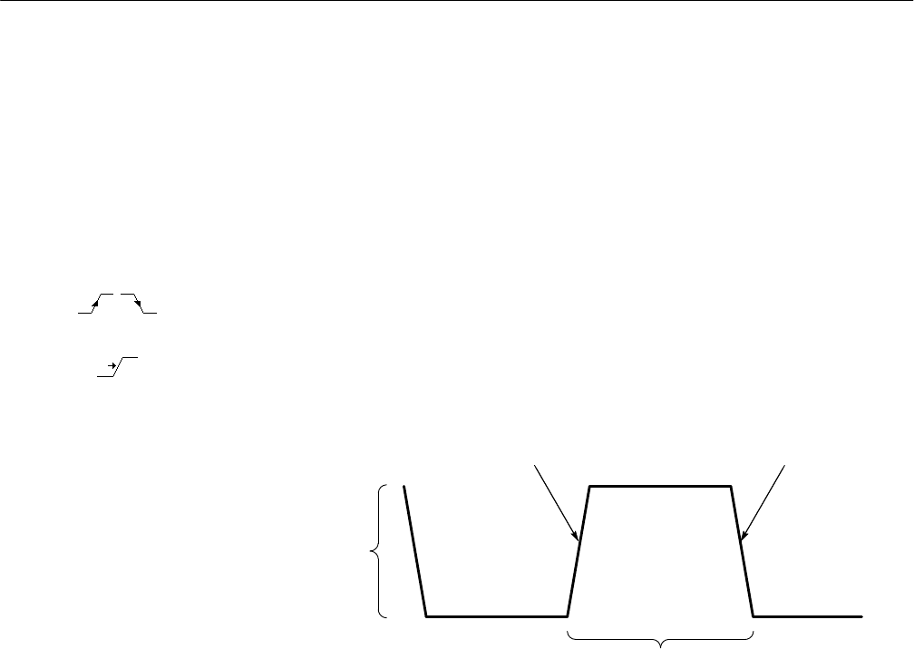
The slope control determines whether the oscilloscope finds the trigger point on
the rising or the falling edge of a signal. (See Figure 3–32.)
You set trigger slope by first selecting Slope in the Main Trigger menu and then
selecting between the rising or falling slope icons in the side menu that appears.
The level control determines where on that edge the trigger point occurs. (See
Figure 3–32.) The oscilloscope lets you set the main trigger level with the trigger
MAIN LEVEL knob.
Positive-Going Edge Negative-Going Edge
Trigger slope can be positive or negative.
Trigger level
can be adjusted
vertically.
Figure 3–32: Slope and Level Controls Help Define the Trigger
The oscilloscope also has a delayed trigger system that provides an edge trigger
(no pulse or logic triggers). When using the delayed time base, you can also
delay the acquisition of a waveform for a user-specified time or a user-specified
number of delayed trigger events (or both) after a main trigger event. See
Delayed Triggering on page 3–80 to learn how to use delay.
Triggering from the Front Panel
The trigger buttons and knob let you quickly adjust the trigger level or force a
trigger. (See Figure 3–33.) The trigger readout and status screen lets you quickly
determine the state of the trigger system. You use the following trigger controls
and readouts for all trigger types except where noted.
Slope and Level
Delayed Trigger System


