Measuring Waveforms
3–98
TDS 684A, TDS 744A, & TDS 784A User Manual
NOTE. When cursors measure certain math waveforms, the measurement may not
be of time, frequency, or voltage. Cursor measurement of those math waveforms
that are not of time, frequency, or voltage is described in Waveform Math, which
begins on page 3–142.
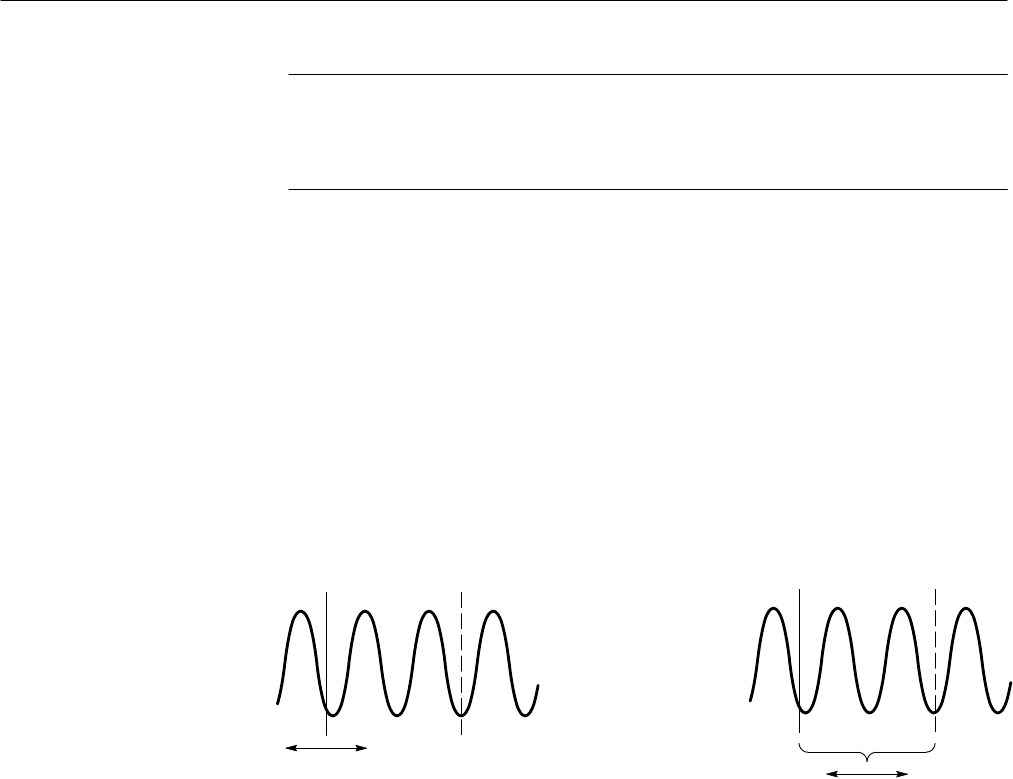
There are two cursor modes: independent and tracking. (See Figure 3–59.)
In independent mode, you move only one cursor at a time using the general
purpose knob. The active, or selected, cursor is a solid line. Press SELECT to
change which cursor is selected.
In tracking mode, you normally move both cursors in tandem using the general
purpose knob. The two cursors remain a fixed distance (time or voltage) from
each other. Press SELECT to temporarily suspend cursor tracking. You can then
use the general purpose knob to adjust the distance of the solid cursor relative to
the dashed cursor. A second push toggles the cursors back to tracking.
Tracking Mode
Only Selected Cursor Moves
Both Cursors Move
in Tandem
Independent Mode
Figure 3–59: Cursor Modes
The cursor readout shows the absolute location of the selected cursor and the
difference between the selected and non-selected cursor. The readouts differ
depending on the cursor type you select, H Bars, V Bars, or Paired.
H Bars. The value after D shows the voltage difference between the cursors. The
value after @ shows the voltage of the selected cursor relative to ground. (See
Figure 3–60.) With the video trigger option, you can also display the voltage in
IRE units.
V Bars. The value after D
shows the time (or frequency) difference between the
cursors. The value after @ shows the time (frequency) of the selected cursor
relative to the trigger point. With the video trigger option, you can also display
the line number.
Cursor Modes
Cursor Readouts


